Eduard's 1/72 Avia S-199s, With Resin This Time
By Chris Banyai-Riepl
Overview
There are some aircraft that it’s easy to imagine building more than one of, such as a P-51 Mustang or F-4 Phantom
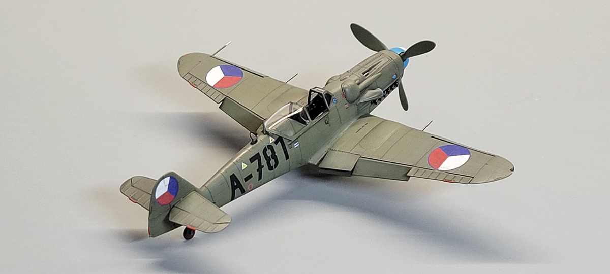
. In my case right now I have multiples of Spitfires, Mustangs, MiG-15s, even Skyhawks. What I never expected was to build multiples of the Avia S-199, but Eduard’s kit changed all that. As nice a kit as it is, it didn’t take me long to have three built up. So when Eduard released their next two boxings of the type, I figured, why not add two more, but this time let’s add some of the Eduard resin detail sets. Armed with cockpit sets and the ETC50 bomb rack, I jumped into building another pair of S-199s.

|

|
The Build
The timing on these two S-199s coincided with my build of the two seater CS-199 (which can be seen here), which gave me a great opportunity to compare the out-of-the-box cockpits to the resin ones. So of course that’s where I started out on these. To add the resin interior, you have to remove the molded-in detail and remove 0.1mm from the fuselage sides. Aside from that step, everything else is pretty much a direct replacement for the kit parts. As these are 3D printed parts, they have a lot of connection points, and some print line textures in some of the flat areas, but the detail is definitely better than the kit parts.

|

|
There is an issue, however, and it’s actually a side effect of having 3D CAD/CAM tooling of both the plastic kit and the 3D printed cockpit set. As noted earlier, the instructions indicate that you need to remove 0.1mm from the fuselage sides, and that number is known because it was precisely measured. Unfortunately, I am not a precision CNC mill, and while I thought I had removed the right amount, I was off. The problem is I did not know I was off until I tried to get the cockpit floor piece in place in the already-glued together fuselage. It was slightly off, which wouldn’t be much of a problem in most cases, but for this kit, the bottom of the cockpit floor also makes up the main landing gear mounting points. The end result is all the alignment was off, which just compounded fit and alignment issues. Nothing too major, and all fairly easy to deal with, but after assembly and comparing the cockpit to an out-of-the-box cockpit, I was quickly realizing the extra effort might not be worth the results. And this isn’t really a complaint over the 3D printed parts but more of a compliment of the molded-in plastic details. These two builds has me seriously thinking about the need for aftermarket in new-tool kits, at least in 1/72, as the quality has just gotten so good.
With the cockpits sorted out, the next step are the wings, and here decisions have to be made on which markings I am going to do. The previous single seaters I built included a dark green one and the civilian-registered one, so for these two I wanted to do an Israeli one and a Czech one finished in the lighter gray-green scheme. Perusing the decal schemes I narrowed those down to the two I will do, and the Israeli one needed modifications to the wings. This plane had a more open wheel well, and this is handled with an extremely useful photoetch template to precisely remove the extra plastic. After a couple of minutes that job was done.

|

|
The next step was to replace the wheel well insert ring with a piece of photoetch, and this started out as a pretty simple addition. Just cut the ring off, thin the lip on the remaining plastic piece, and add the photoetch. However, there was one major issue that caused no shortage of frustration, and that was no bend lines on the PE part. I was left to try and figure out where to bend this one long piece of photoetch that needed two sharp corners and two straight runs that then curve in. With no reference marks anywhere, I tried a couple of different ideas. The first was to try to use the template provided for cutting the hole as a template to find the bend points. That didn’t work much at all, so I then tried using the template to cut some card stock to shape and attempt to wrap the photoetch piece around that template. That didn’t work well either, so I ended up just manhandling it in place. That resulted in something far from perfect, and required quite a bit of extra work filing down to get the wings together.

|

|
Still focused on the wings, the next step was the wingtip lights. On my previous builds I didn’t spend much time on these, just got them to fit as close as possible. This time around, I decided to get them perfectly flush, which meant doing a lot of polishing work. I painted the inside edges to mimic a light bulb, then used CA to firmly attach the clear parts. After attacking those with sandpaper in increasingly finer grits, the result was a nicely blended in wingtip light. Some careful masking and the wings were ready for painting.
The final construction item before heading to the paint booth involved the landing gear. Unfortunately for me, the challenges continued as upon inspecting the kit parts I discovered that one landing gear leg had the top mounting portion broken off. This is one of the engineering aspects of this kit that I previously loved, as how Eduard engineered it ensured perfect alignment with a sturdy mounting point. In looking at the part on the sprue, I vaguely remembered seeing the broken part in the bag, but at the time I didn’t put two and two together and realized I needed that part, so it got tossed along with the bag. So, no choice but to create a fix.

|

|
The first step was to get the corresponding landing gear from the second kit to see where the break happened and determine just how much I needed to replicate. I initially thought I would re-create the entire top leg structure, including the large peg that slides into the corresponding slot, but I realized I really didn’t need to do that and would risk getting alignment issues. So I just recreated the top portion and cut it to the correct length. To do this, I first drilled out the top of the leg, and inserted a piece of plastic rod as both a strengthening feature and an alignment feature. On top of that I slid a piece of tubing that was close to the right diameter of the landing gear strut. With that in place, I then trimmed the new strut top to the correct length, using a template I cut from card using the unbroken strut in place to get both the right length and right angle set.

|

|
Finally, Painting & Last Steps
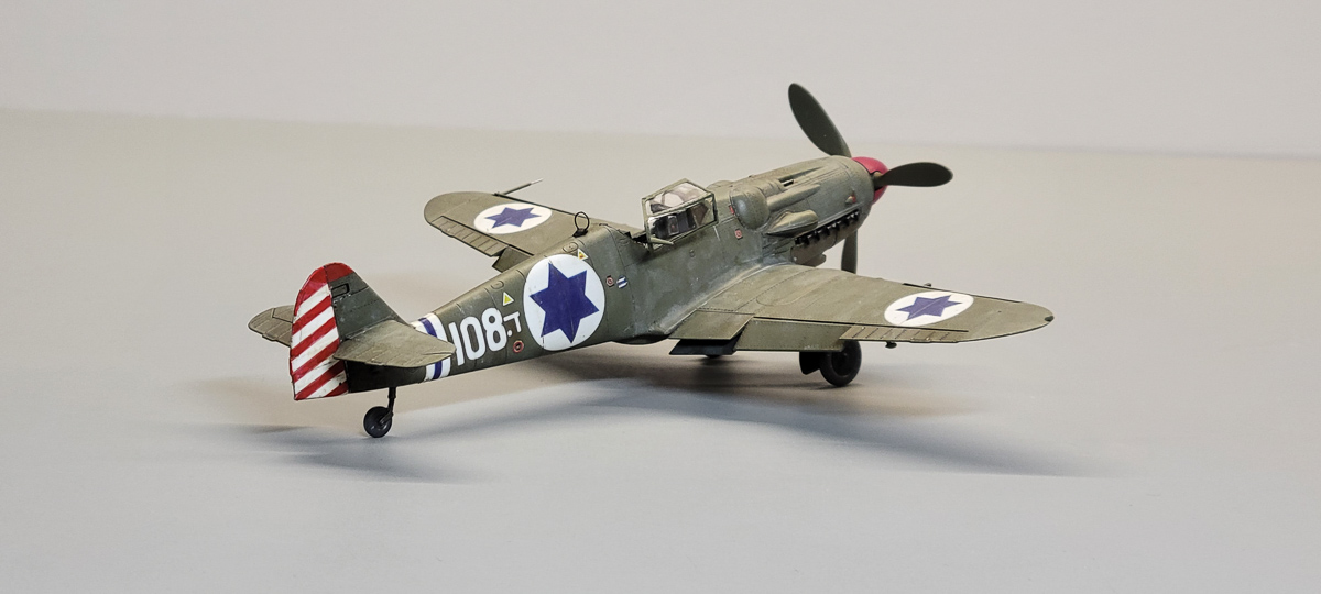
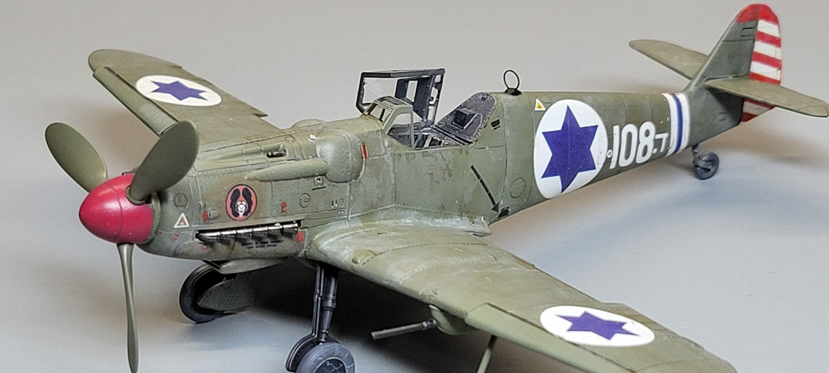
For both of these aircraft, the base color was the same, that being a gray green overall color. While the Czech option was left in a fairly uniform color, the Israeli option I wanted to be much more weathered as it was operated in a much harsher environment that included combat operations. I realized that this would require layers of weathering, so I started that process by going back over the base gray green with a lighter color airbrushed in a random pattern. I then repeated the process with another shade, this time a bit darker, with the result being a nicely subtle effect that I knew I could build on with additional weathering techniques after the decals were applied. At the same time I also painted the cowl underside a different color, as that was called out in the instructions. I used the same darker color for the aftermarket underbelly bomb rack, for additional color variation.

|

|
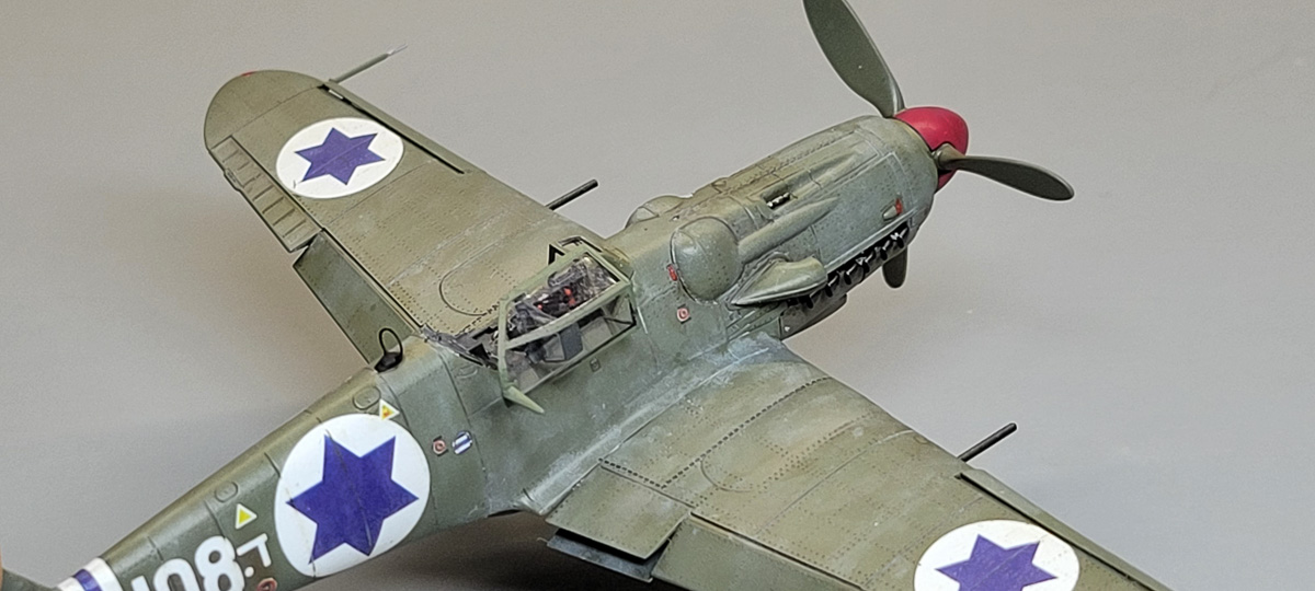
After glossing things up, I turned to decaling. These went down flawlessly, and the comprehensive set of stenciling added that extra layer of realism on the models. Both options had cowl markings, with the Israeli having a squadron emblem and the Czech example having a red lobster. A simple panel line was applied to both, and for the Czech example that was about the limit of weathering as I wanted to keep that one fairly clean. The Israeli one, though, got more weathering in the form of layers of dust that then had areas of rubbing away, resulting in a very well worn look.

|

|
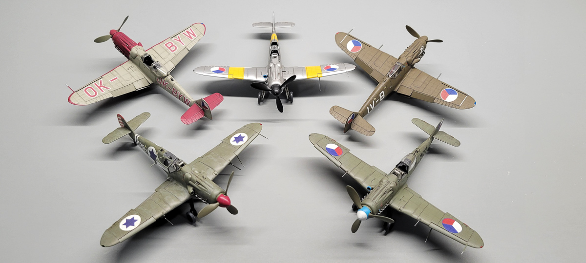
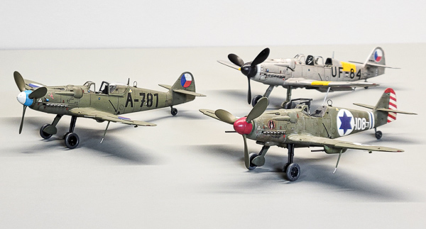
The final assembly included adding all the landing gear pieces, sticking the canopies on, and adding the propellers. The Israeli S-199 also had the underwing cannon gondolas, which were weathered slightly less than the airframe for yet more variation on that option. The only thing left is some antenna wire rigging, but unfortunately I was out of my thread for that, so I’ll be coming back to that once that shows up. And with these, I now have examples of just about every camouflage option for the S-199 out there, making for a pretty interesting display.

|

|
Conclusion
I had never thought I would build more than one or two S/CS-199 models, and here I am with five built. Despite the challenges I had this time around, these kits remain the best choice for 1/72 Avias and Eduard’s building on these kits with new Bf 109F & G kits will mean many, many more of these builds in my future.

