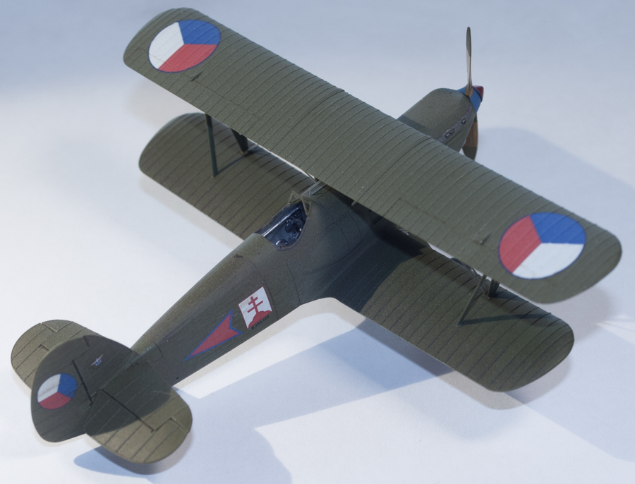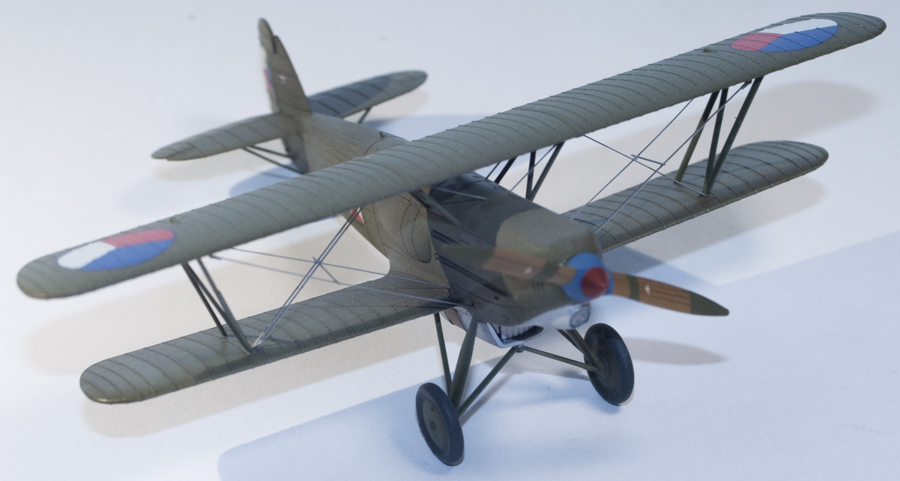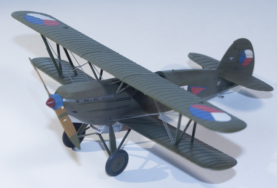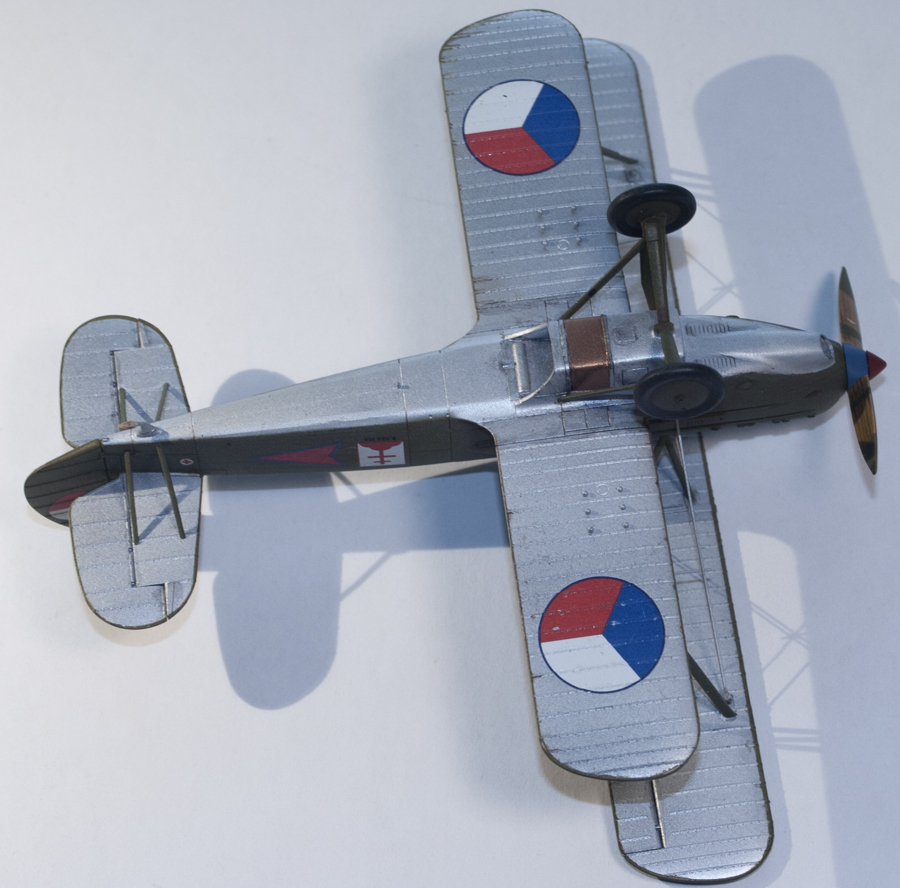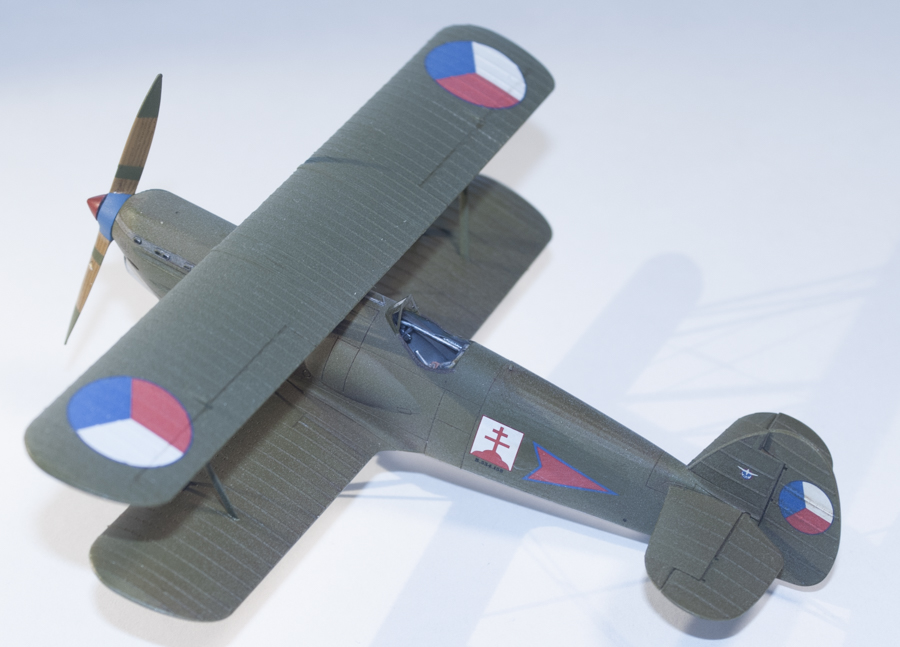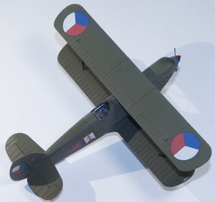
Eduard 1/72 Avia B-534 III. serie Weekend Edition
By Matt Bittner
Introduction
Eduard has embarked on a large Avia B-534 project, producing kits in 1/144, 1/72, and 1/48 scales. There have been other 1/72 Avia B-534 kits in the past, the first one I remember being the older KP kit. It wasn’t a bad kit even if it was released in the 1970s and can still be built today; however, with the level of detail – and ease of assembly – of the Eduard kits, building the KP kit would definitely take more time and resources.
In the recent past two other companies produced really nice 1/72 Avia B-534s, HR Model and RS Models. Both are also worth building if you have them as you can see with Curtis Knight’s build of the RS Models kit. However, the level of detail and fit of the Eduard kits also surpass those two company’s models.
I used two primary sources for my build. First and foremost was the book Eduard provides with their Royal Class (RC) boxing of the kit. While the entire text is in Czech the photos proved to be invaluable. It was one of these photos that will help me finish the IV. serie kit I’m working on now. Another resource was the book put out by MBI which contains excellent drawings, photos – some of close up details – and color profiles.
The Kit
As with all of their Weekend Edition kits Eduard only provides the plastic, instructions and decals for two aircraft inside the box. Along with the kit I also used the Weekend/Zoom photoetch set, separate masks and rigging developed specifically for the Eduard Avia B-534. I decided early on to finish it as a different aircraft than provided for in the box, the decals coming from the RC boxing since that release contains markings for 29 aircraft and only three sets of sprue in the box (the fourth in the RC box is the Swiss racing example which the plastic can only be finished as).
Construction
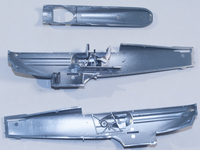
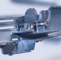
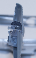
Naturally construction starts with the cockpit and since I was using the Zoom (Weekend) photoetch set that needed to be taken into consideration. The Weekend photoetch set contains seat belts, trim tab control wheel for one side of the cockpit, additional rudder pedals and a much better looking instrument panel. There are also two other internal photoetch pieces to be aware of: a radiator face to be added to the front of the plastic piece (E6/16) as well as a fold-up radiator intake vanes to replace the thicker, plastic pieces. The biggest advantage with these is they can then be posed in other positions to give the model a more dynamic look. However, there are two things you need to be aware of with this photoetch piece. First, make sure these vanes are “closed” as you build the model. First-hand knowledge shows if these are left in any “open” configuration you will handle them while building and could break them off. Second, you’ll want to affix the bottom of the piece, under the vanes, to the kit part. This will also help keeping the vanes in place and will help with the re-positioning later on.
|
|
Since the interior was overall aluminum I sprayed the parts with the new Vallejo Aluminum which really sprayed well. I applied a wash of black oil color and picked out a few parts in different colors inside the cockpit. Since the photoetch instrument panel and seat belts were pre-colored there was no need to paint those and they really enhance the cockpit.
|
|
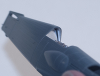
I’m not sure if it was me or the kit, but part B6 – the bulkhead behind the pilot’s seat – left a gap that needed to be dealt with. Thankfully I was able to use Perfect Plastic Putty (PPP) to fill it, which meant no sanding, but it is in an awkward location and not easy to clean.
|
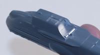
Once all the interior pieces are mounted to one fuselage half the fuselage halves can be assembled. Take your time and if you’re careful you can get away with little-to-no seam filling. I still had one area that was troublesome, and that was the underside rear-fuselage, right past where the radiator exhaust is. This is how I discovered – after the fact, of course – there is supposed to be a “step” from just aft of this area to the section of fuselage right before the “fabric” area starts. Unfortunately dealing with this area I broke off the small, raised piece (which I think in real life was some sort of “drain”) so had to restore that after I finished sanding that area. In fact, everything that was molded in-situ on the fuselage I broke off. All antenna stubs, “drainage tube”, etc., so had to replace everything. This goes hand-in-hand with taking your time and being careful with this aspect of assembly.

|
Before proceeding with the next steps, and since I was using Eduard’s own photoetch rigging for the model, I needed to drill holes for the “stretchers/eyelets/turnbuckles”. Eduard recommends using a .03mm drill bit but that turned out not to be wide enough and went with a .035mm bit; however, since a couple of rigging frets I have are actually not “in register” I would actually opt for a .04mm bit. It might be a little wider than the “eyelet” but when using thick CA to glue these into the holes they will be filled with the CA. One thing I did that I was glad of was put tape around the drill bit, where the bit needed to stop, so I wouldn’t drill through the wing. You’ll notice that Eduard molded-in small “pips” where these “eyelets” are to go into the wings. Take a very sharp blade, remove the “pip” then drill the hole. For the fuselage holes just follow Eduard’s provided instructions on where to measure and where to drill.
Now that all those holes are out of the way construction commences. I glued the tail parts on (with no filler needed at all) and slightly deflected the stabs. I wanted to deflect the rudder but I’ve broken it off twice now that it will only stay straight (note to self: don’t handle the model by the rudder). I also attached the lower wings, paying attention to the instructions on the actual dihedral needed and again, no filler was needed. Also added at this time was the upper, forward-fuselage nose but this time a little bit of filler was needed, thankfully it was just PPP so the excess was wiped away with a damp brush.
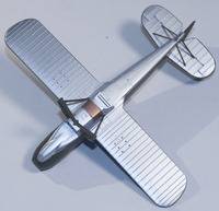
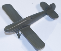
The model was now ready for painting. The top green wrapped around a slight bit to the underside so while the separate Weekend masks do not provide them, the Royal Class kit does provide masks for the wing tips. Both sets do include masks for the horizontal tail pieces which is nice, but why Eduard doesn’t provide the wing-tip masks on the separate mask set is beyond me.
|
After priming the model with Vallejo gray primer I then sprayed the underside with Vallejo’s newer Matte Aluminum paint and it went on wonderfully. Once dry I then masked most of the underside and sprayed the “brass/copper” onto the radiator using Formula P3 “Molten Bronze” – produced by Privateer Press (a miniatures company) – which looked excellent. It too was masked once dry and the upper surfaces were sprayed. Eduard’s color call-out seems to me quite “khaki-ish” so I looked in my paint stash and decided that Polly Scale’s “Fr. Khaki” (505238) was a better match (I will spray the next Avia with Eduard’s recommended paint for comparison).
|
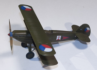
Since I decided to use one of the marking options from the RC kit it was time to spray the prop and spinner. After that was accomplished everything received a coat of Future prior to decaling. The decals went on really well with just using MicroSol on them.
Now for the fun part: adding the upper wing and applying the photoetch rigging. Gluing the upper wing on to the struts was actually the really easy part; rigging, not so much. It was mostly because I didn’t get all of the holes re-drilled to remove the paint so some of the “eyelets”, or “turnbuckles” came out as I was trying to fold the ends of the rigging around the “eyelets”. And this too is an issue: be sure you have fine tweezers where the ends actually meet together so you can fold the ends of the rigging around onto itself. Hopefully my next one will go a little better in this area.Before applying the final coat I added the photoetch gun sight and tried to add the pitot tube to one of the struts. Unfortunately I cut the tube from the fret too close to the tube so it didn’t work. Another lesson learned the hard way. Once the rigging was finished then it was time for an overall Vallejo flat coat and adding the windscreen and pilot’s step.
|
Conclusion
The Eduard 1/72 Avia B-534s are excellent kits and with the right amount of patience will turn into stunning miniature examples of the real aircraft. Hopefully my trials-and-tribulations will help others out there, not just for myself for all the other kits I have.
Huge thanks to Eduard for the review items.
(Note: I just realized the pilot's step came off in the photos <sigh>.)
Lessons Learned
When I started this serie. III build I also started a serie. IV Weekend kit at the same time. The following lessons I learned while building both side-by-side (but ended up concentrating on this serie. III in the end).
- The area at the aft-end of the fuselage underside radiator outlet is not supposed to be flush with the rear fuselage, there is a ledge
- I ended up with gaps with the insert into the rear of the radiator and the rear cockpit bulkhead, and used Perfect Plastic Putty and took a brush to “wash off” the excess. Whether that was a problem with my assembly or not I do not know, but I have the same issues on a 534 Serie 4 I’m working on
- If using photoetch radiator intake grills, leave them “closed” during construction; do not position them until you’re ready to paint and apply the final over-coat; however, definitely position them before the final over-coat and even before painting. But, for this to work the bottom photoetch piece that attaches to all the “vanes” needs to be firmly bent and glued to the plastic
- Don’t cut the photoetch pitot tube too close to the actual tube; leave a little bit of the “fret” to ensure the pitot tube wraps around the strut
- Using the photoetch stretchers and rigging has its own issues:
- One extremely helpful tip I discovered was to use a piece of tape on the drill bit to stop from drilling all the way through the wing. There is no guesswork this way and you can drill until you reach the “tape-stop”. But ensure each hole is the same depth and ensure the stretchers are all at the same height when you glue them in
- Eduard recommends a drill bit of 0.3mm; I would go with at least a 0.35mm if not a 0.4mm
- Pay close attention to the photoetch; I had one set of stretchers/rigging that appeared to be off-register: one side appeared to be “fatter” than the other side. If this is the case then you’ll definitely need a hole of at least 0.4mm for the stretchers
- Thankfully Eduard provides extras of all pieces; enough so that if you’re careful you can rig two models with one set of stretchers and rigging
- Of course you’ll want to drill the stretcher holes before painting; however, also re-drill after painting. You want a very good hold on the stretchers into the hole so you don’t pull them out while rigging which is why it’s also best to use thick CA to attach the stretchers
- For this one I glued the stretchers on/in after I attached the upper wing; the next one I’m going to try and attach the stretchers before adding the upper wing and before adding the inter-plane struts
- Do NOT anneal the photoetch. Trust me on this
- Bending the end around the stretchers is its own form of “interest”. Take your time and ensure you have a sharp pair of tweezers in which the ends of the tweezers actually meet together correctly
- Naturally, too many times bending any of “posts” on the end of the rigging that go into the drilled holes will result in those posts snapping off. This is not the end, though, especially with the center-section rigging. I actually found it easier to use these sections with the posts removed then trying to get it all lined up. But still drill the holes as this well help with rigging placement and you’ll be able to hide the holes with the rigging. Where the posts really help are the inter-plane rigging that ends into the fuselage
- Before adding the cross, interplane rigging (part number 5 on the Eduard fret) ensure both sides of the interplane rigging are at the same angles on both wings, otherwise if you look head-on at the model one cross-rigging wire will appear higher than the other side

