Avro 1/72 V2-9 Avrocar: A Hat Trick of Meh
By Morgan Girling
John "Jack" C. Frost had an impressive CV, including designing the deHavilland DH.108 Swallow before joining Avro Canada in 1947, where he worked on several projects before starting the Special Projects Group – an R&D group within Avro. In 1953 (2 years before Christopher Cockerell in the UK), the SPG had discovered that ejecting a sheet of high-pressure air towards the ground from the rim of a disk created a cushion of air which lifted the disk off the ground. Further research showed that the more one deviated from a disk, the lower the performance, which led to a series of designs (Project 1794 and weapon system WS 606A) for a supersonic disk aircraft using an air cushion as its landing gear. These designs garnered funding from the USAF, and a subscale research vehicle, the VZ-9 Avrocar also got funding from the US Army as a "flying jeep" armed with an M40 recoilless rifle.
The Avrocar used a central "turbo-rotor" – a free-spinning fan driven by the exhausts of three J-69 jet engines blowing through a drive rotor on the outside rim of the fan. The air brought in by the fan and the jet exhaust from the drive turbine was routed through an annular duct around the underside of the disk, providing a cushion of air which would raise the disk. As it rose out of ground effect, the curtain of high-pressure air would cling to the underside of the disk due to "Coanda effect" and form a lifting column in the center. Once the disk was about 1.5 diameters (27') above the ground, guide vanes in the ring slot would pivot to direct the ejected air rearwards. Calculations showed that this subsonic testbed should reach about 235 miles an hour and climb out to fly like a normal aircraft.
The rollout configuration was comparatively sleek, with two bubble canopies and the jet engines drawing their air from the pressurized air downstream of the turborotor. it also featured a round "bumper" rim that acted like a wing slot, drawing air from above when the compressed air was directed downwards. The first prototype was sent to the wind tunnel at Ames Research Center, while the second was kept in Malton, Ontario for flight tests. Testing showed that the design didn't live up to the calculations. Despite the vanes inside the ductwork, the engines ingested some of their exhaust, reducing the already marginal power, preventing it from rising from ground effect. The controls to steer the ejected air lacked command authority, so response was sluggish. Finally, the wind tunnel tests showed that the "bumper" and slots caused aerodynamic problems in forward flight faster than 30 mph. (The bubble canopies were removed and faired over to simplify the wind tunnel testing.)
|
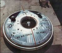
Engine performance was largely restored by switching the engine intakes to the top of the disk. The upper slot was faired over to improve aerodynamics, and an articulated "focus ring" was added to the underside to better direct the air towards the center in hover and aft for forward flight. The bubble canopies and their fairings were removed and replaced with simple rollbars because the cockpits became very hot from the greenhouse-like bubble canopies and waste heat from the turborotor seeping into the cockpit.
|
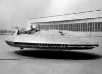
As performance improved, more problems revealed themselves: as the Avrocar started to rise, it became wildly unstable ("hubcapping"), solved by adding 12 extra pressure jets near the center. The focus ring didn't produce enough forward thrust, so they added 12 ejector ports to the trailing edge of the disk, and soon these sprouted control vanes for stability and more control authority. Soon this was supplemented by additional ports along the sides to direct more air aft.
The Kits

|
Fly Models No.72015
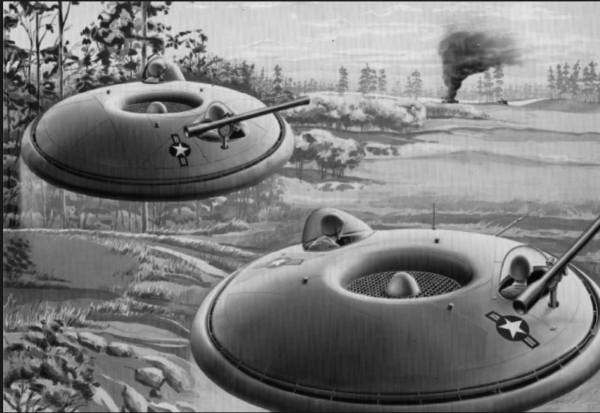
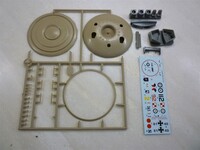
There are many boxings of this kit - mine had somewhat lurid box art, showing a pair of saucers with external "bazookas" in entirely spurious markings. The back of the box shows equally spurious markings and colors for various nationalities. Inside is a resealable bag containing the single sprue of 23 parts, molded in tan plastic, another bag containing 10 well executed resin parts, another bag holding the 2 "clear" canopies, plus an instruction sheet and decals. The saucer is primarily an upper and lower half, featuring delicately recessed panel lines. The rest of the parts consist of the underside focusing ring, the landing gear, and the turborotor. Reflecting the saucer's many test configurations. it can be made with or without canopies and there is a blanking plate for the starboard cockpit. Oddly, it omits the roll bars used when they removed the canopies. The resin parts are nicely detailed resin cockpits and seats, side ejector ducts, and inlet moldings for the 3 jet engines. Some of the vanes on the side ejector ducts had broken off in shipping, but the bag kept them from being lost. Vacuforming new bubble canopies would be a big improvement over the slightly murky, too-thick kit parts. In all, it looks like a nice, quick "palette cleanser" of a model.
|
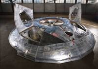
The kit seems to be based off of the #1 prototype used for wind-tunnel research and which now resides in the Museum of the USAF. This has the aft ejector ports moved to the front, a smaller turborotor intake and a set of hefty support vanes for the turborotor "spinner", and identical bubble canopies on each side. Museums try to do their best, constrained by budget and reference material, but at a minimum, the canopies are wrong – they should be upright, not canted out like bug-eyes.
|
I've found no photographic evidence that the aft ejector ports were moved to the front, and since they were designed for forward motion, it doesn't make sense to move them to the front as that would fly it backwards. However https://www.gettyimages.ca/detail/news-photo/avro-canada-vz-9-avrocar-vertical-takeoff-and-landing-news-photo/639810484 explains this: at some point Avro turned the disk around in the wind tunnel, with the covered cockpits at the rear. The propulsive slots were then added to the new "rear" as was a T-tail for stability. The tail was removed before the Avrocar was placed in storage, and the Museum of the USAF didn't realize the propulsive slots were on the wrong end when they restored the vehicle.
Sharkit
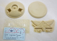
At first glance, the Sharkit is a good representation of the rollout configuration, and the turborotor is the correct diameter. Molded in tan resin as upper and lower halves, plus seats and cockpit details, it features nicely vacuformed canopies + hull section, and decals. Not only are the canopies wonderfully clear, but they're also handed, and this is the only kit that allows you to easily model it with the canopy open, though the seats aren't quite right. Overall, a good representation, especially if you scribe some of the panel lines that were omitted.
However, it seems a trifle small and frankly pudgy. It should scale out to 3" in diameter but is only 2.800", which is very noticeable. It also omits the ground handling "landing gear, though it would be trivial to scratch-build.
It looks a lot like the US Army publicity illustration, so if you add an M40 recoilless rifle, you've got a plausible model and a defensible backstory.
|
Shapeways
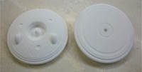
The final player is a 3D printed offering from Mitchell Jetten via Shapeways. This consist of one (1) part in a powdery white resin with exaggerated panel lines, topside jet intakes and solid (but handed) canopies, and the turborotor is the right diameter. On the demerit side, the canopies are opaque and a little narrow. Like the Sharkit, it is missing the ground handling landing gear. You'll also need to fill in the jet intakes on the upper surface and the hole in the underside (used to drain out the uncured resin). As soon as you prime it, however, the surface roughness becomes apparent, and it takes several coats of Mr. Surfacer, sanding in between applications to get it smooth enough to use.
It looks a little thin, which is odd because the profile matches the sectional view shown below. And there's the rub. That sectional drawing is wrong. When compared to photos of the #2 prototype in flight, the photos show a thicker disk. The Avrocar should scale out to 3" diameter and 0.613" from the top of the inlet to the bottom of the "bumper", while the cross-section has a height of 0.597".
|
So, What Can One Do?
None of the models is accurate in height, with Fly and Shapeways being close approximations of the cross-section drawing. The only photos I've found of VZ-9 with canopies is the rollout configuration with the "bumper". The wind tunnel faired the canopies over and the flight test removed them entirely. All 3 models have the same diameter for the outer lip of the turborotor intake, so your options depend on which variant you want to produce:

|
Rollout: The Shapeways is the closest, but you must either live with opaque canopies or make a resin casting and vacuform canopies for it. With the canopies closed, not much can be seen of the cockpit, so routing out cockpit holes and adding WWII fighter seats isn't beyond the pale. The print is hollow, so one could probably cut it along the equator with ease. It's a bit thin but not objectionably so. The "bumper" support struts are a too thick, but easy to cut away and replace with brass wire. You also need to fill in the jet intakes on top, add fuel tank caps, and source your own decals and landing gear. All in a day's work.
US Army illustration: Sharkit is your best bet, adding an M40 recoilless rifle (try Model Miniature MM-R037). You'll have to source your own decals and landing gear.
VZ-9 #2 flight test: Using the Fly kit, turn the bottom half 180° and use the facets on the rear as a file guide to reproduce them on the top. Similarly, use the smooth curve on the bottom as a guide to putty in the facets on the front top. Of course, this means the tricycle landing gear is backwards, so one would need to fill the 3 holes for the landing gear and drill 3 new holes to restore the gear to the correct location. And one would need to cut open the panels that cover the cockpits and bend a couple of roll bars from brass wire. Cut out the turborotor intake at the outer diameter of the lip (there's a panel line) and replace it with a copy made from either the Sharkit or Shapeways turborotor. It's still a bit thin, but the Fly has superb engraved detail.
VZ-9 #1 in Ames wind tunnel: Use the Fly kit modified as above to put the 12 ejector ports at the rear (or not) and replace the turborotor. Fair over both cockpits, remove the landing gear and build wind tunnel support struts (pictures can be found online). It is still too thin.
VZ-9 #1 at the Museum of the USAF: Use the Fly kit as-is, adding support vanes to the turborotor (the drawings on the rear of the kit box are fairly accurate, but double check with online photos of the museum copy).
References
Avro Canada VZ-9 Avrocar, https://en.wikipedia.org/wiki/Avro Canada VZ-9 Avrocar
https://www.laesiworks.com/ifo/lib/AVRO-Car.html (good collection of photos)
Zuk, Bill. Canada's Flying Saucer. Boston Mills Press
Frost, J.C.M. Proving Out a Flying Saucer. Canadian Aviation, July 1961 pp.14-18
Frost, J.C.M The Canadian Contribution to the Ground Cushion Story. Canadian Aviation Journal, Oct. 1961
Garland, D.B. Avrocar Continuation Test Program Instrumentation Specification for Ames Tunnel Tests 1st Avrocar Vehicle. 500/Aero Test/415 Issue 2, December 1960
