Scratchbuilt 1/144 Caudron R.XI
By James Gray
 |

 |
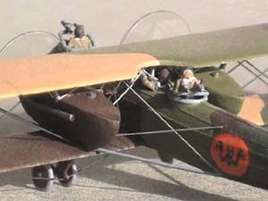 The cockpits were going to be occupied, so I was able to leave out any internal detail. It's just as well, since I have not been able to find out anything about the interior at all. The cockpits are basically drilled holes, painted black inside. After that, I had to deal with the very prominant fabric-over-stringer covering. Apparently the fuselage is like most Allied aircraft fuselages, a simple square framework of wood braced with wire, but the Caudron company completely enveloped this with a streamlined shape of light stringers with doped fabric over that. I stretched some sprue until I had enough of a consistant diameter, then glued this over the fuselage in the stringer locations using liquid cement. This is the first of this sort of work I had done with liquid cement, and I was pleased to find I had a minute or so to push the sprue into place before the glue set.
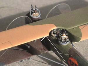 On to the wings! The wings were not too much trouble but they are not quite what I wanted, either. I cut them out of sheet plastic, not as thin as they ought to be, but as thin as I thought I could get away with. One of the compromises I was compelled to make in this scale was between the desire for scale thickness and the need for a little rigidity. I scraped and sanded an airfoil shape into the top of the wings, rounding the leading edge and making a long taper on the trailing edge. The bottom of the wings was scraped with a curved-edge pocket knife to a noticably convex shape, though because of its excessive thickness, the airfoil is by no means accurate. Then came the hard part, the highly visible scalloped effect caused by the wire trailing edge. These scallops need to be shallow and of exactly even depth and spacing. This is hard to do. So hard, indeed, that I never succeeded in doing it. I did get a pretty fair 'batplane' effect, but this wasn't what I was trying for. Eventually I decided that no scallops were better than badly done scallops, and I made a new pair of wings without them. The lower wing was then inset into a square notch in the fuselage, and the fuselage below the wing was built up with many layers of paint.
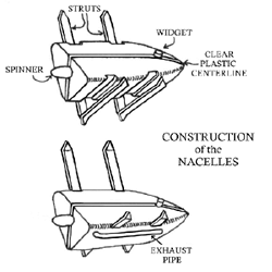 The two nacelles were another challenge. I didn't see how I was going to manage them so I just started at the 'shallow end of the pool', which is to say that I did what I knew I could do and left the rest to be worked out later. This is not very efficient but sometimes it's the only way. Anyway, the nacelles are a very peculiar shape, sort of like a brazil nut with the end cut off. Carving one shouldn't be too bad, I thought, but carving two identical ones would be another matter. It was easier than I thought because of a discovery I made when I was laminating the plastic to the right thickness; I glued the blanks around a center piece of thin clear plastic and this gave me a permanent center mark that could not be effaced by any amount of carving or sanding. In the end, they were not so difficult and came out quite well.
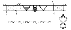 Now you have a biplane, but very fragile. The assembly does not become strong until you have the rigging installed. Because I didn't know quite how to install the engine nacelles yet, I rigged the outer wing cells on both sides first. For this, drill very small holes in the proper locations for the rigging attachments. I use #80 bits unless several wires are to go through a single hole. Then I take some pre-painted invisible thread. This is a very fine nylon thread available in sewing shops, equivalent to about one pound fishing line. It is said to come in a semi-opaque ìsmokeî shade, but I've only been able to find the clear, so I paint it either silver or black with a paint pen. Run the thread through one hole and glue it. Apply the thinnest superglue you can get to the outside of the hole; that is, the top of the upper wing or the bottom of the lower wing. This keeps you from messing up the paint job between the wings. Once the glue is set, stretch the thread taut. I hang a fly-tying clamp on the end of the line, but a clothespin would be about right, too. I apply glue in the same way as before to the outside of the wings. Work back and forth to equalize the stresses on the wings so you don't get things warped out of shape. Its amazing how much strength and rigidity this gives to the rather limp plastic wings.
 Of course, there are two pairs of these front to back on each wing. Now, the problem of how to install the nacelles on these struts! any good modeller should be capable of devising a simple, effective, efficient method of doing this. Unfortunately, I was doing this project instead. I cut four rather wide grooves vertically in the side of each nacelle, lining up more or less with the struts. This wasn't very neat, and I had to put them in and take them out and cut on the grooves some more quite a few times until I got the nacelles to fit properly down over the struts. Unfortunately, this meant that now there were these great big gouges in the sides of the nacelle, which I filled with putty and sanded until they were flush. Because of the confined space involved, this was a very messy and time-consuming job, and only fluent cursing gave me the fortitude to complete it. Fortunately, my Navy time gave me the necessary experience in this regard. It messed up the paint job between the wings too, and I had to repaint that as well.
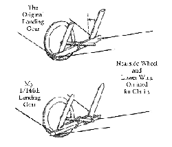
 The wheels were another item I didn't see how I was going to manage. I couldn't cannibalize wheels from one of the white-metal 1/144th scale kits I had, since these are never actually round. I finally found I could make my own. I wound a spiral of plastic Evergreen rod around a dowel of about the right diameter, then boiled it. When it came out of the hot water, I cut a line down the line of the dowel, through the coils of the rod. The result was a series of plastic rings. I punched out several disks and glued these rings (tires) around them and voila! Wheels. I built up the outside of the wheels into a blunt cone (as are real WWI wheels) with layers of paint and a little sanding. The complex landing gear struts are brass wire bend and superglued into shape. As with the wings, the rigging provides a lot, perhaps most of their strength. The wheels are in pairs on a short horizontal axle, one on each side of the strut assemblies. I tied this axle to the strut assembly with fine wire. This seems an odd solution, but there was an advantage; since the short axle can pivot around the strut assembly, there is no problem getting all four wheels to touch the ground. When adjusted, a drop of superglue keeps the wheels from flopping around.
 The last remaining concessions to the Caudron's origin as a gaming piece are the clear disks for the propellers. These were simple enough, made by turning many circles with a sharp pair of dividers on clear plastic. These never seem to come out perfect, always picking up a scratch from somewhere, but a dip or two in Future floor polish improves that to the point the scratches are almost invisible.