Flashback 1/72 Sopwith 1 1/2 Strutter
By Matt Bittner
History
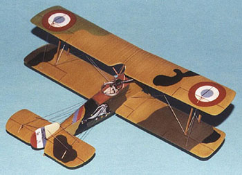
Even though the Sopwith Land Clerget Tractor - or commonly referred to as the 1 1/2 Strutter - was designed and built by the British Sopwith Aviation Company Ltd., it was the French who used it more, and manufactured the most number, approximately 4600. The French used it primarily as a two-seat reconnaissance plane (1.A2), a two-seat bomber (1.B2), or a single seat bomber (1.B1).
|
Unfortunately, while the French used it the most, there is very little photographic evidence left of French Strutters. This is a real shame since the French had the most colorful Escadrille, or squadron insignia.
The Kit
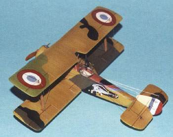
Flashback have recently released kits of both the single and two-seat version of the Sopwith 1 1/2 Strutter. The Flashback kit of the Sopwith 1.A2 Strutter consists of 27 injection-molded pieces on two main sprues; three blocks of resin consisting of 6 pieces; two pieces of clear plastic for the windscreen mounted on the gun butt and the instruments; and one sheet of photoetch brass. The decal sheet provides markings for two aircraft: Collishaw's Strutter of No. 3 Wing RNAS; and a 1.A2 of the French Escadrille SOP 226.
|
The kit of the double seater kit can be built into two versions, one French and one British. When choosing an option, one also chooses which parts to use. Parts that are used on the British machine are: part number 6 resin Clerget 9Z; part number 17 propeller; Scarff gun ring on the observer's cockpit; and the cut-out upper wing. For the French option, the following parts are used: part number 5 Clerget 9B; part number 16 propeller; Scarff or Nieuport gun ring dependent on the machine; the upper wing without the cut-out; and the plate that fits behind the cowl underneath the fuselage (photoetch part number 12).
This kit is a dream. It is complete in almost every respect, and can be built to represent a Strutter out of the box. In fact, it is probably the only WW1 kit I can think of that can be built out of the box, and represents the real thing as best as possible. The only thing missing is the rigging material.
|
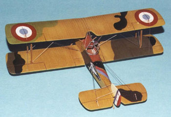
Construction naturally starts with the cockpit. Everything that is needed is contained within the kit. However, there is still room for the super-detailer to add their personal touches. Granted, the pilot's cockpit can not be seen once the top wing is on - especially if you build the French version - but the observer's area is there for all to see.
Once the resin floor is cut off the "pour block" and cleaned up, then painting and basic construction can commence. The sides of the cockpit should be a Clear Doped Linen (CDL) color, while the support structure should be wood colored. After painting the pilot's seat an off-white color to represent wicker, then the photoetch seat belts can be added. The cockpit consists of the resin floor (which also contains the fuel cell behind the pilot, as well as the pilot's and observer's seats) and resin control column (a photoetch one is provided, but is much too two-dimensional looking); photoetch interior fuselage sides, rudder pedal, pilot's seat belts, engine "blip" switch, and horizontal tail control wheels. Also included is a photoetch instrument panel to which is glued on the back a clear plastic sheet which contains the instruments resulting in a most realistic instrument panel. All model instrument panels should be manufactured in this fashion.
After all cockpit parts are painted and assembled, then the fuselage halves can be glued together. Little putty was required in this area. Unfortunately the putty that was required was on the turtledeck behind the observer which resulted in the removal of the top-most stringer. This stringer was later replaced by cutting a groove in the fuselage with a panel-line scriber, and adding some .010" Slaters rod, finishing with some light sanding to bring it down to scale.
|
Now the panel can be added that covers - and defines - the observer's area. A little putty was required here. Careful dry fitting will help alleviate the worst of the problems. (This is where Flashback provides the two seater versus single seater option. For the single seater, this area is covered with a piece that looks like an extension of the turtledeck.)
Unfortunately my kit contained a molding flaw in the starboard wing root on the fuselage. Part of the fuselage root was faired over, which had to be scraped and sanded so the starboard lower wing half would fit. This also meant a poorer fit than the port wing, which resulted in more putty being required for this area. The wing to fuselage joint was also enhanced by slicing off the molded in pegs - which are to fit in holes in the wing roots - and replacing them with brass rod. I also went a little overboard ensuring a strong joint in this area. Once the brass pegs were inserted into holes drilled into the wings, this area received a different treatment than I have given wing-to-fuselage joins in the past. I CA'ed the brass pins into the fuselage, used tube glue on the plastic-to-plastic join, then brushed liquid cement over this area once the two plastic pieces were together. Once this all dried, I then ran a bead of CA over the joint. This provides a very strong joint.
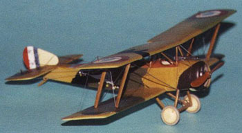
|
The kingpost was then added. Unfortunately, it is one of two areas Flashback left off. A slot was filed into the rear of the fuselage, being sure to leave plastic on top and bottom. Then a piece of brass rod was added to represent the control structure that changes the incidence of the horizontal tail. After the rod was added, then a piece of plastic was added to the rear, to "cap off" the whole area.
The other area Flashback left off was the exhaust channel under the cowl on the underside of the fuselage. This was easy to add by just filing in the appropriate area.
Fortunately, Flashback modeled one aspect of Sopwith aircraft that would be difficult to replicate. This is the area of the turtledeck in front of the horizontal tail which - for lack of a better term - "swoops up" to meet the horizontal tail. So far this area has been missing from all other kits of Sopwith aircraft.
I decided to dress up the area of the fuselage under the horizontal tail. It's difficult to describe, but the leading edge of the horizontal tail actually sits on a piece that's "faired into" the fuselage under the tail. This results in an at-rest stance of the horizontal tail looking like the front is sitting higher than the rear. Since the real aircraft's horizontal tail's incidence could be adjusted, there is a very noticeable gap between the tail and the fuselage (IPMS judges or not). I also dressed up the fin by replacing the plastic pin with more in-scale brass rod, and made sure the gap was noticeable here as well.
Since the cowl was painted in the same colors as the fuselage, I painted the engine, glued it on then added the cowl to the model before painting. There was no other construction difficulties. Unfortunately the Lewis gun was ruined while removing it from the pour block. An excellent replacement from Rosemont Hobby Shop - in their Roseparts line - was substituted.
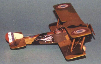
|
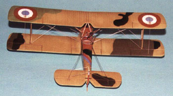
Rigging is .005" stainless steel "surgical" wire. Unfortunately, Flashback forgot to document in their excellent rigging diagram two "wires" found on the real aircraft. There were wires running from the top of the rear-most center strut (at the inverted "V") down to directly in front of the observer's cockpit, terminating at the "corners".
The colors were gleaned from a photo of SOP 287's line up. The colors are my best guess, and any errors in the colors - or the layout of the colors - are all my own. The port side is a complete guess, since no known photo's exist of this side.
Conclusion
While the two areas that Flashback left out - the exhaust channel and kingpost - are major omissions, they have molded a most distinctive - and difficult to replicate - Sopwith feature, which is the "up-sweep" the turtledeck takes in front of the horizontal tail. This is a huge plus in Flashback's favor.

|
This kit was fun. Not only building it, but also tracking down reference material proved very enjoyable. That's what it's all about, isn't it?
References
Sopwith 1 1/2 Strutter: Datafile No.34; Albatros Productions Ltd., 1992
French Air Service in World War 1; Flying Machines Press, 1997
