Summary
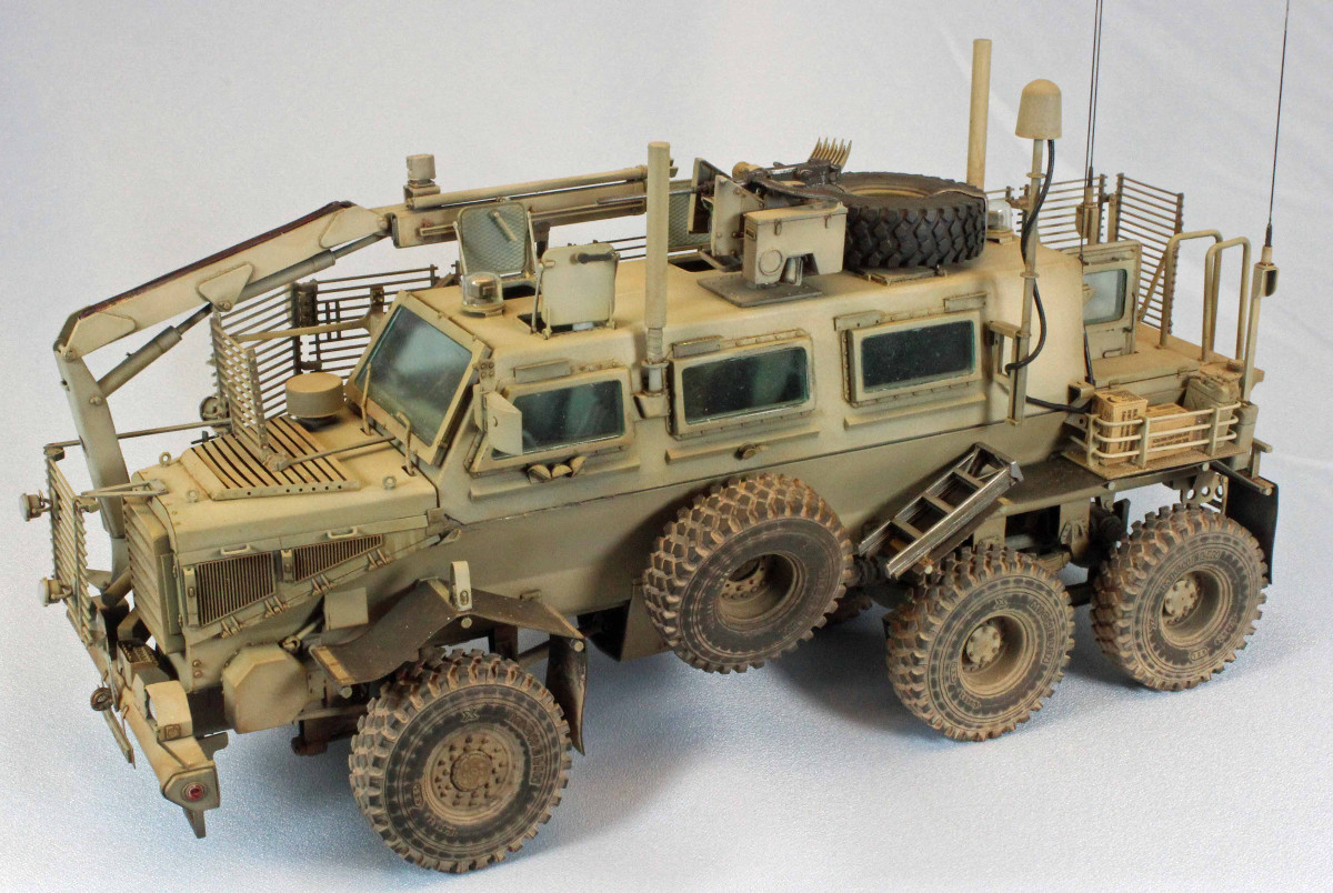
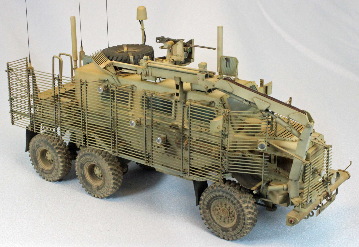
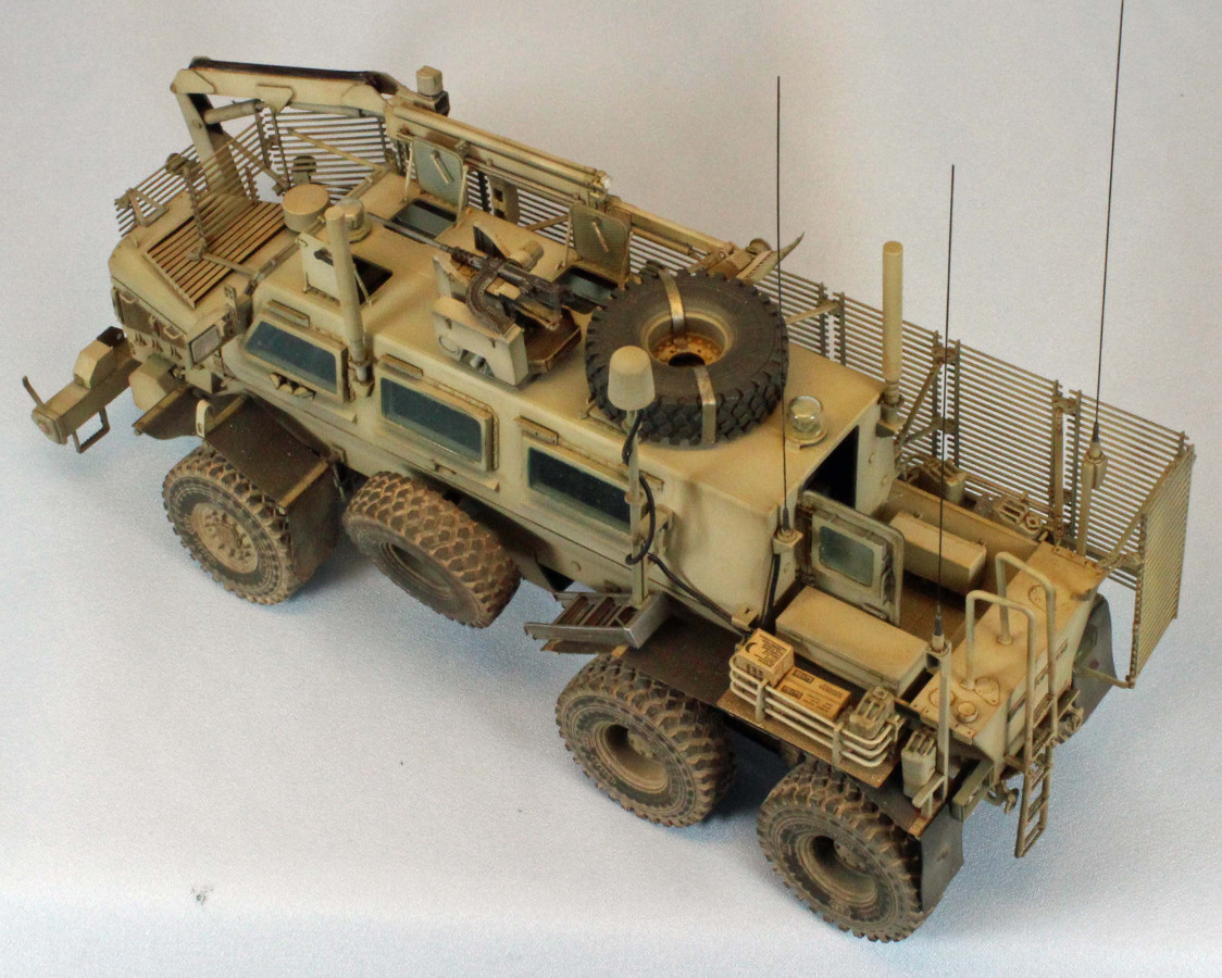
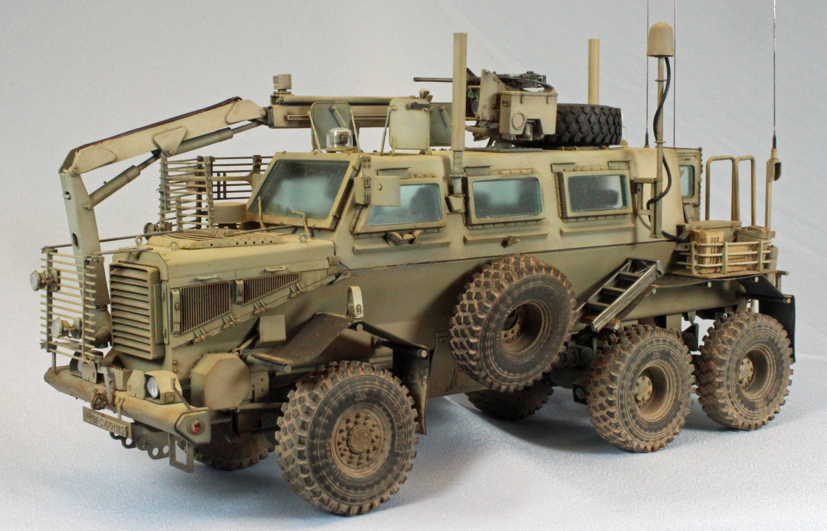
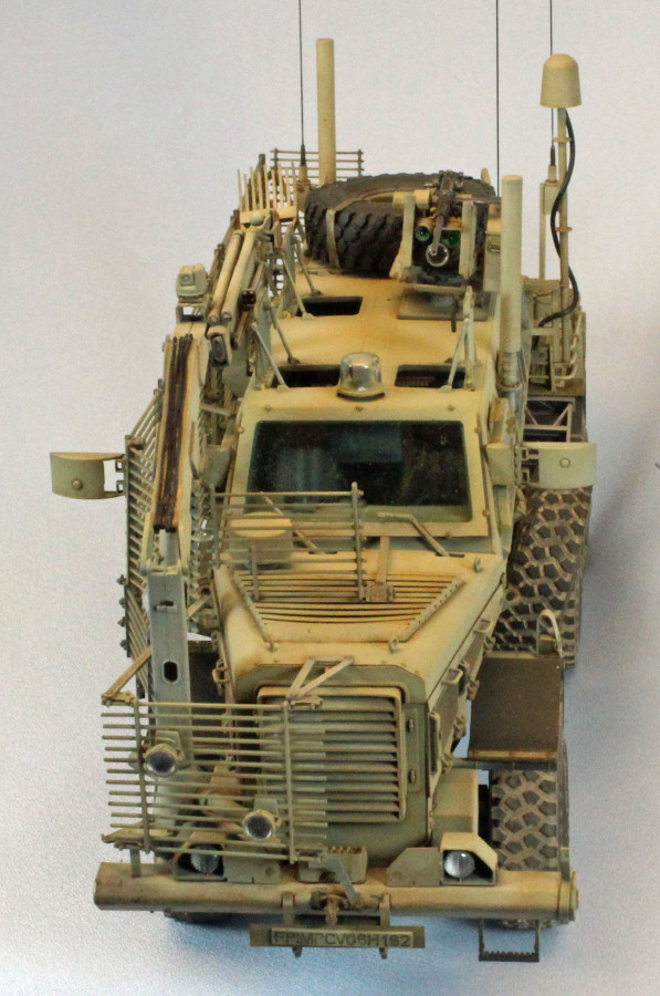
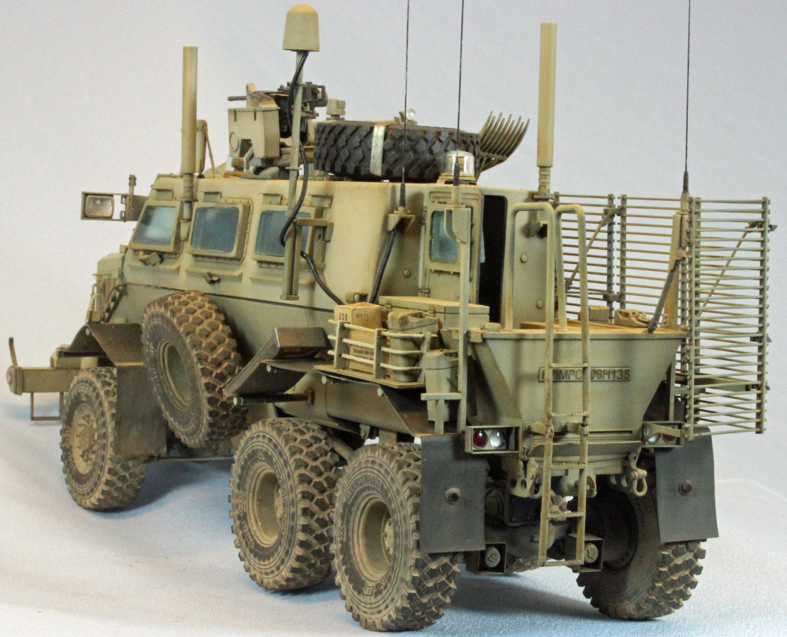
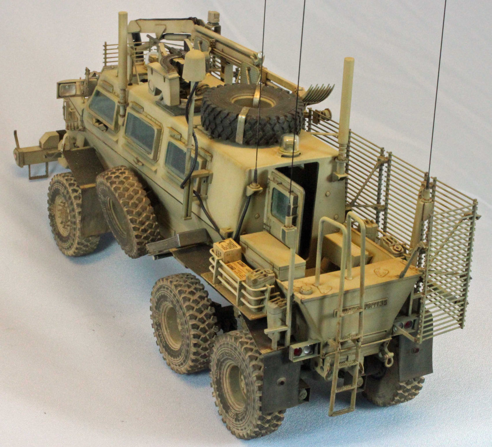
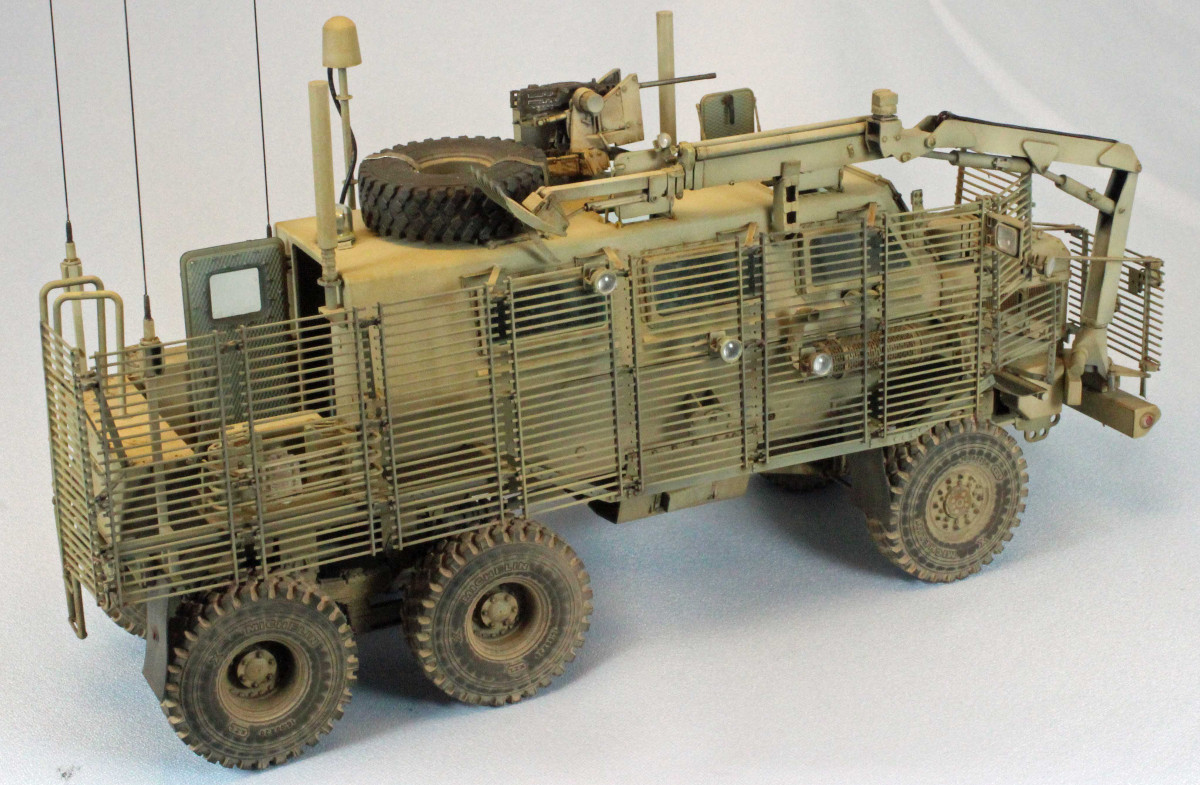
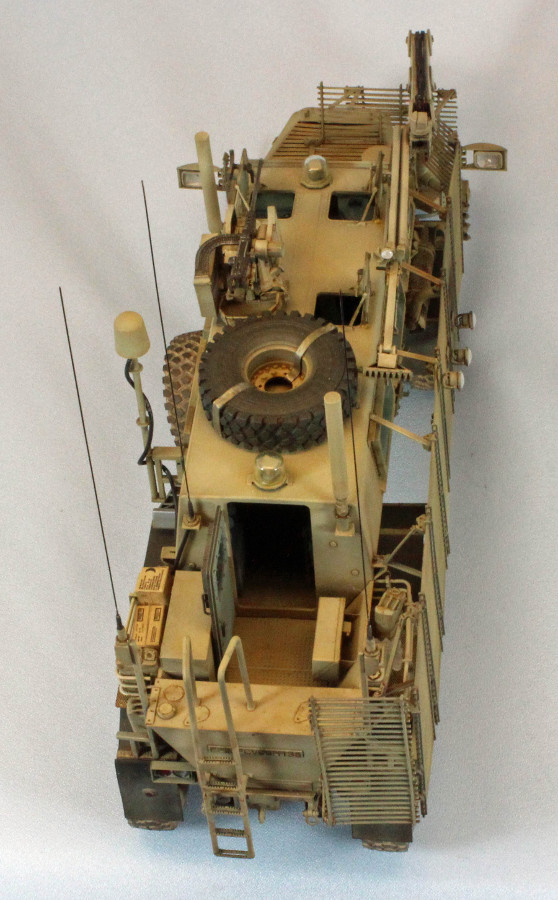
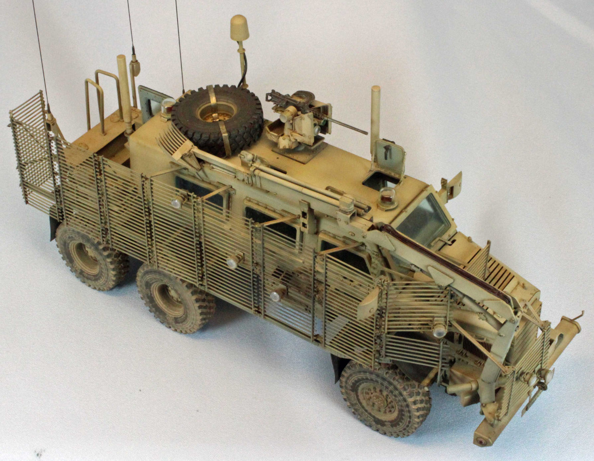
Bronco has released its second version of the Buffalo 6x6 MPCV (Multi-Purpose Crew Vehicle). This incarnation sports a complete set of Slat (Cage) Armor used to defeat rocket projectile weapons such as RPGs (Rocket Propelled Grenades). This release includes the XM153 Crow II System close-in defense weapon and two types of armament. The slat armor installation precludes the use of some of the antennae, the spare wheels, and other prominent parts found on similar vehicles without the armor. These parts are still included in the kit, however.
Background
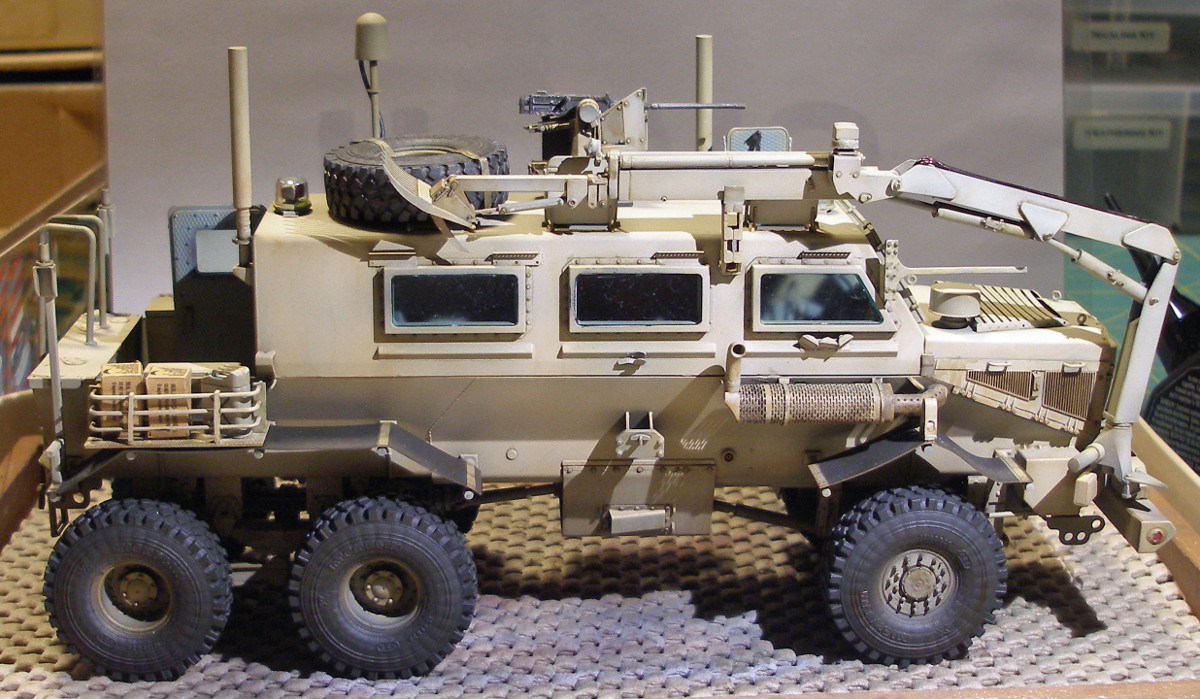
The Buffalo MPCV (Multi Purpose Crew Vehicle) was based on the successful South African Casspir mine-protected vehicle. While the Casspir is a four wheeled vehicle, the Buffalo has six wheels. The MPCV is also fitted with a large articulated arm which is used for ordnance disposal. Both vehicles incorporate a "V" shaped mono-hull chassis that directs the force of the blast away from the occupants. The Buffalo depicted in the Bronco kit is equipped with BAE Systems' LROD cage armor for additional protection against RPG-7 anti-tank rounds. The glass armor is sufficient at 6 inches thick. Run-flat tires are present on all wheels. The Buffalo combines ballistic and blast protection with infrared technology to detect the presence of dangerous ordnance and a robotic arm to disable it. Personnel operate the Buffalo's 30-foot robotic arm and claw from within the armored hull via a mounted camera and sensory equipment, to safely dispose of mines and IEDs.
In 2004, the United States had a limited number of Buffaloes in service, with an order for 15 more, at a cost of $10 million. Force Protection, Inc delivered its 200th Buffalo to the U.S. Military on June 6, 2008. Force Protection started work on the A2 version in 2009. The A2 featured major changes in the Axle Tech rear axles, Cat C13 engine and CX31 transmission and suspension, along with addition upgrades to the HVAC system, hood and the front bumper. The easiest way to identify an A1 version from the A2 version is the front bumper: that of the A2 has a larger profile. The last Buffalo A2 truck 795 was completed in June 2014. General Dynamics Land acquired Systems Force Protection in 2011.
Opening the box
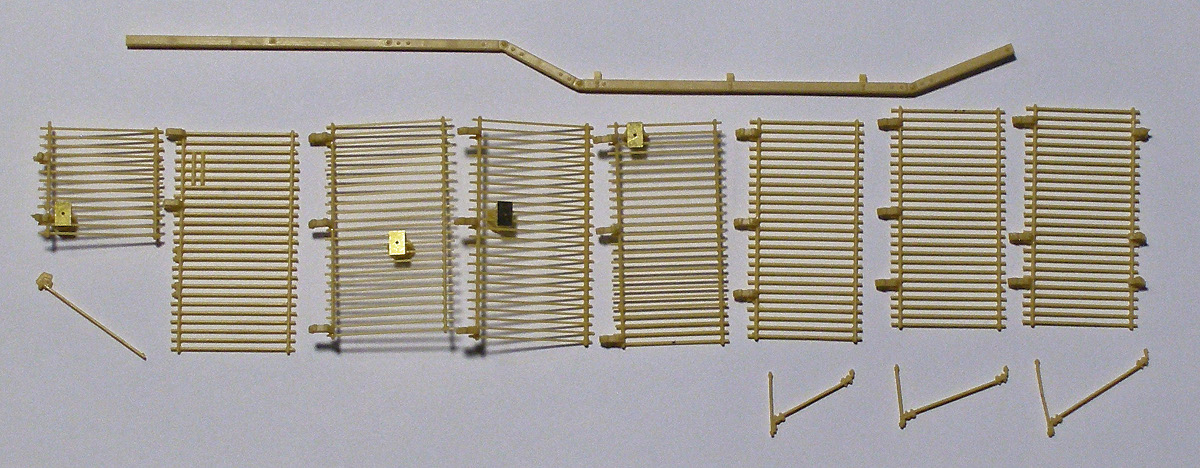
There are a LOT of parts in this kit, but nothing we haven't seen before from Bronco. The oversized, cardboard box is not as sturdy as you might expect for the number of parts, but the contents reached me intact and undamaged. I dreaded looking in the box at first, knowing that the vehicle had a full array of slat armor: who knew how the cage armor was would be rendered? I was pleasantly surprised, however, to find the delicate sections of armor beautifully engineered in super-thin plastic, completely free of flash and sporting attachment points at the ends of the bars, requiring virtually zero clean-up. Very nice!
Most parts are used and since there were so many sprues that the first thing I did was label each sprue using masking tape and a Sharpie to make the sprue identification letters stand out. This helped things tremendously during the complex build.
The contents of this box include:
20 sprues in soft, light tan-yellow plastic, packaged separately.
5 sprues of clear plastic parts (windows, water bottles and lights), packaged separately.
8 outer tire treads, packaged separately.
Lower and upper hulls, packaged separately.
1 50-cal gun casing, packaged separately.
A baggie containing two thicknesses and lengths of soft, plastic black piping.
1 large photo-etch sheet, sandwiched in thin film plastic to help cutting and removal.
1 35-page color instruction booklet containing highly detailed CAD color and B/W drawings, with 59 assembly steps.
1 small (but perfectly registered) sheet of decals from Cartograph of Italy.
The Instructions
Like so many other Bronco kits the instructions come in a beautifully rendered, fully illustrated, color 8.5x11 booklet. The CAD images are sharp and they show the assembly from a variety of different angles to help the modeler through the build. However this is a complex kit of a complex vehicle. It is relatively easy to have things go sideways unless you pay very close attention to what you are doing. There are parts included that are unique to the Canadian version and these are not identified, other than to say that they are optional, so a little up-front work is in order to figure out what you want to do.
The instructions come with a single finishing scheme representing an 'unknown' unit. There are specific paint call-outs for Mr. Hobby, Hobby Color, Humbrol and Tamiya paints, and a nice, two page section showing the vehicle and the XM153 Crow II System in 5-view color images to help with painting. The assembly sequence varies by modeler but the general flow of things goes pretty much as Bronco intended. The exceptions I made are identified in the text below.
Up-Front Decisions
The Buffalo build is broken up into three phases: the interior, the exterior, and the cage armor. Each of these phases need to be completed and weathered before starting the next one. The exterior itself is further broken into two parts: what you do before starting the interior and what you do afterward. The "build-it-first-and-then-paint-it" approach won't work with this kit.
Bronco has included an abundant amount of articulation in many areas, especially the undercarriage and mechanical arm. Unfortunately, even if you don't want moving parts on your model you'll still have to incorporate most of the articulation anyway (at first) simply to find out where and how the next 'chunk' fits. Once you complete a particular assembly you can move it to where you want it into position and add glue to fix it in place. This can be frustrating, especially with the undercarriage. But don't give up! Once in place, it looks great.
You need to make some other decisions before starting, including:
What version do you want to build?
Do you want to leave the top hatches and back door open or closed? If you choose the latter option you can leave 90% of the interior in the spares box: it won't be visible on the final product.
Do you want to use the XM153 Crow II System? It covers up a hatch and has some special parts associated with it to install in the interior.
What parts do you need to leave off until after the major assembly is done and finished, such as the clear parts, mechanized arm, antenna, wheels, mud flaps, fenders, exterior equipment, muffler, cage armor, etc.?
Needless to say, building the Buffalo requires a lot of planning, both up front and as you go along.
The kit contains a lot of parts that have (male) connection tabs, but their (female) counterparts are not holes, if they exist at all. They are very small indentations in the surface receiving the part in many instances. As a consequence, the part often doesn't seat correctly and it stands proud of the surface. You can either deepen the indentations or sand down the tabs to fit. Either way, test fit everything before applying glue.
I almost passed on building this kit because I felt the slat armor would hide this robust-looking vehicle's impressive lines. The armor also prevents the installation of the prominent spare wheels, the neat dome-shaped antenna mast and a lot of other interesting detail. In the end I decided that I would install the armor on half of the vehicle to provide insight on how that comes together while still allowing the other half to be built without it. I therefore moved some of the detail from the starboard 'armored' side of the vehicle to the port side so it would not be lost behind all those bars and support structure. My Buffalo won't be entered in a contest, but it will provide an interesting conversation piece on the Display Only table!
The Build
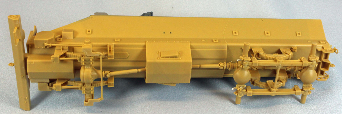
Steps 1-11: Lower Hull and Chassis
The kit construction starts with the lower hull and chassis. The four cable stanchions (Assembly 1) are meant to be moveable, but I glued them with the cables pointing straight downwards. The placement of Part B9 is vague, and later on, important. The images in Steps 8 and 10 are helpful here. In Step 2 there is no need to articulate the leaf springs. If you look ahead to the next step you can see these glued down in place. This is good, because I don't know how you can glue the parts together and still make them moveable.
The four box assemblies in Step 4 are a challenge if you follow the instructions. I recommend using the following procedure instead:
Bend the photo etched parts into a box.
Drop the oil seal into the box and secure it with super glue.
Cover everything with accelerator.
While that is still wet, carefully dip each edge of the box into a puddle of super glue to create four solid edges.
When dry, carefully sand each flat surface with a padded sanding stick.
Drill a hole in from the rear big enough for a (shaved down) post (Part E46).
Dry fit.
Glue the post to the axle and let dry.
Repeat this step 3 times.
Attach all four boxes and pose them, gluing plastic to plastic. I left this last step until much later in the project so I wouldn't snap them off while handling.
In Step 5, be careful. The two axles have a long and a short portions, so be sure to attach them so they line up with each other. Steps 5 through 8 are daunting. I was distracted at some point and I put things together incorrectly. I had to disassemble these parts and start over. If you are slow and methodical things will eventually come together. Thank goodness that the fit of the parts is excellent, and that Model Master's "black bottle" liquid cement dries slowly!
Step 12: The Wheels
The design of the eight huge wheels in the kit is nothing less than brilliant. The deep tread comes as a hollow plastic ring that slip over the sidewalls of the tire which then is pushed on to the wheel – an ingenious design that insures the integrity of the bold tread pattern of the tires. After assembling the wheels, I set them aside until near the end of the build, after weathering.
Attaching the wheels
Inexplicably, with wheels so large and prominent, they do not attach with a firm, confident 'chunk', but are somewhat wobbly, not helped by all the articulating hardware they are mounted on. I ended up gluing two wheels at a time, using a lot of Model Master 'black bottle' (read: slow-drying) cement, and babied them until they stood 'reasonably symmetrical'.
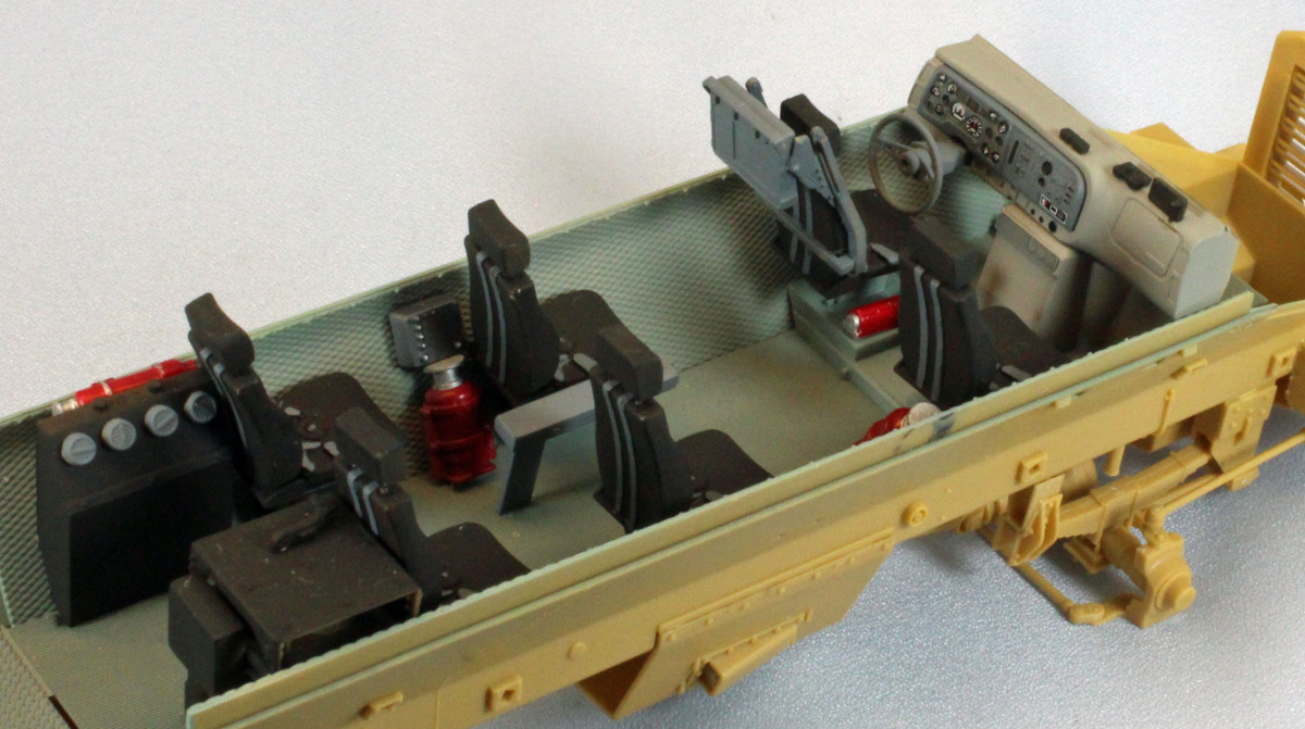
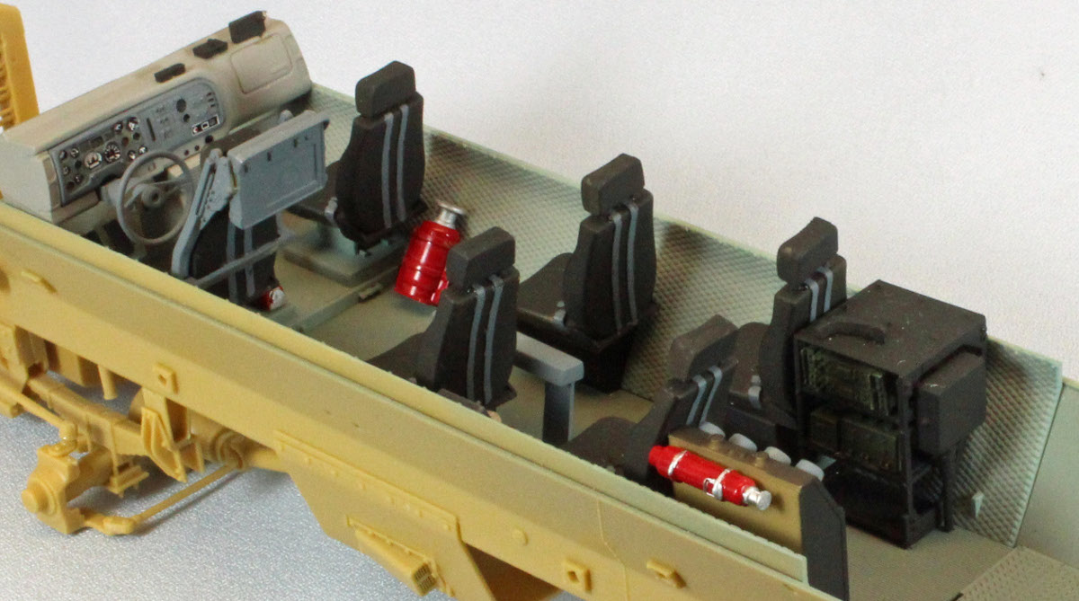
Steps 14-22: The Interior Cabin
Bringing the interior cabin together was reminiscent of building an airplane model. Assemble and paint, assemble and paint. I painted nearly all of the separate parts and assemblies before attaching them to the interior hull. See the "Interior" paragraph in the Painting section below for the colors that I used. The two sidewalls and the floor in Step 14 have a very tight fit. I had to sand off material from both sides of the floor to get the sidewalls to slide in behind them and I still had a real tight seal between the three pieces. I also had to shave off part of both fire extinguishers (parts E71) to keep the floor from bowing underneath where they attach. When you finally attach the floor, make sure that the little stubs for the seat bases (parts F13) line up perfectly with the tiny cutouts in the floor.
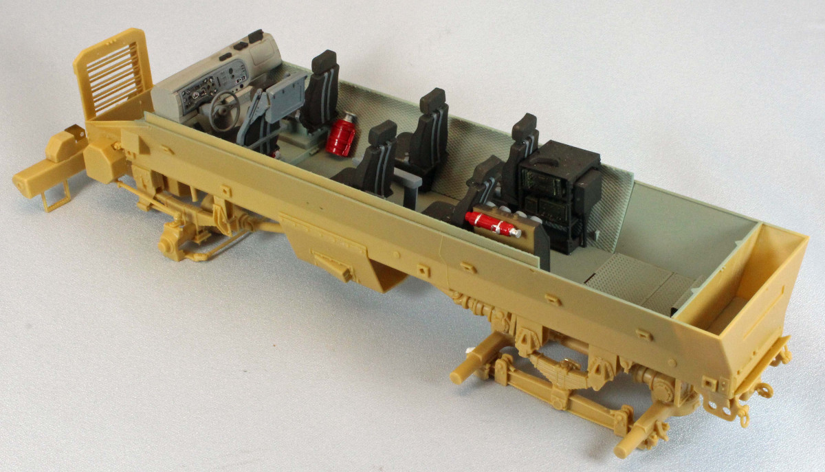
There is some play with the floor and it is easy to get these misaligned. The placement of the four photo-etch parts in assembly 13 is vague. The image in step 22 is helpful here. Step 16 will have you assemble and attach the steering wheel. The angle of the steering column will become apparent if you wait until step 22, when you can attach it to the dashboard before sliding both into place in the hull. It's actually fits perfectly then. The assembly labeled 17 in step 19 is a real challenge to align. Luckily the whole thing just peeks out from the doorway and is mostly hidden from view. The detail of the parts is excellent, however.
In steps 21 and 22, the stowage bin in assembly 21 appears to be new in this kit, since it does not appear in any image I can find of the Buffalo 6x6 without slat armor. It is made up of two triangular sections and it forms a squared-off storage bin, rectangular in shape. Since the placement of this bin is vague at best, I looked through the rest of the instructions to catch a glimpse of where it should be placed, only to find that in every other image this bin in shown as only one half of the assembly attached directly to the sidewall, instead of the full assembly attached using the two PE supports. My bin was already glued and dry, so I attached it about midway vertically in the space provided. You attach the seats in step 22, but using the hidden attachment points is an exercise in futility. I shaved off the attachment points and simply glued the seats in place where I thought they should go.
XM153 Crow II System (roof-mounted close-in support weapon)
The XM153 comes in two assemblies, the gun itself, which sits on the roof over the center port-side escape hatch, and the control center, which is attached to the back of the driver's seat and is operated by the passenger who sits directly behind the driver. I suggest you wait and build the control center in step 27, when it is actually attached to the seat and floor instead of in step 21, which the instructions dictate. That way you will know where it will be fitted and you can assemble it accordingly. The weapon itself was a disappointment. Like the vehicle, the Crow II has a lot of parts but unlike the vehicle the fit is poor. The tiniest of dimples serve as joining points between significant pieces, if they were present at all. It seemed to me that no matter how slow I went, or how long I stared at the instructions and images, I could not get things to line up properly. In the end, I let the five or six sub-assemblies dry completely, cobbled everything together, and then whittled and bent things so that horizontal lined up with horizontal, and vertical with vertical. I decided at this point that the vehicle would not be entered in a contest and that I could therefore leave off half the slat armor. That was a relief, really.
Water Bottles
I just couldn't pass up the water bottles, but how could I easily create a 'six-pack'? Answer: drop three bottles onto the gummy part of a Post-It note and line them up. Then smear a thin coat of Gator's Grip Hobby Glue (sort of a Elmer's Glue 'on steroids'), and then drop the second set of three bottles on top and line everything up. The glue will hold fast and dry crystal-clear.
Steps 23-24: The Front Bumper and Hood
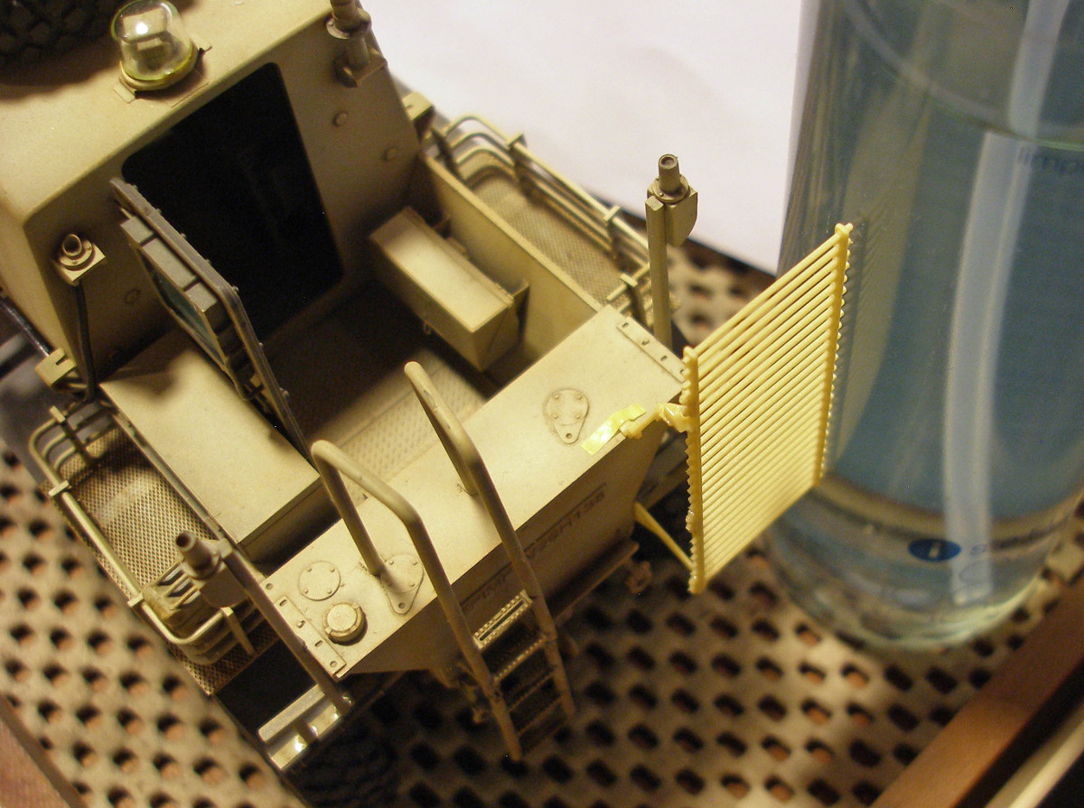
The front bumper contains a lot of delicate photo-etch that is prominent in such a visible location. I had to perform a little plastic surgery to get the headlight covers (parts P18) to fit. You can save yourself a lot of hassle by attaching part D54 (from step 34) now, before attaching the bumper to the vehicle's front. In step 26 the front hood comes with a prominent photo-etch grill that, like most of the other p/e in the kit, does not have a plastic alternative. Bending the front of the grill is tricky and you only get one shot, which I took and missed. I wish Bronco would consider plastic alternatives for p/e-challenged modelers like me, especially for high-visibility applications such as this grill.
Steps 25-26: Upper Interior Cabin and Ceiling
The fit of the two side panels of the upper interior (parts A11/A12) and the rear panel (part A4) is very tight. Too tight, in fact. You can attach the side panels first or the rear panel first; either way you'll have to shave some material off something to get things to fit.
Step 30: Step ladder
I don't know what Bronco was going for here, but it seems like the design team got a little out of control with the aluminum step ladder. No fewer than eight separate layers sandwich together to form a sold chunk of ladder-looking plastic, finished off with a top that doesn't quite fit and four tiny pieces of photo-etch. Really? Moving on.
Step 33: Exhaust muffler
The exhaust muffler is gorgeous when completed, but it presents a challenge getting there. It sticks up and out of the busy starboard side, from beneath the right-front window. Like many other parts on this model, it is a multi-media affair, with three pieces of p/e and a pipe extension out from both sides of the muffler. It would be difficult to build and attach this assembly if you follow the instructions. I suggest you proceed in the following order:
Glue Parts C2 and C3 together and let dry.
Wrap and fix the p/e skin (P16) the above.
Wrap and fix the two p/e bands (P2).
Attach what you have so far to superstructure under the right-front window and let dry.
Now that you have the exact orientation of the muffler, attach the extension pipes on both sides of the muffler.
Step 37: Rear Deck
I had problems with the fit of the rear panel on the rear deck (part U3). First, when the small nub facing forward slipped into its receptacle on the hull, the rear of the part stuck way out over the edge. I looked at some photographs and other images in the instructions convinced me that this part should be flush with the rear hull. When the part was seated it wasn't level, and it was also tilted slightly aft, because the top edge of the inner firewall (part A5 from step 15) wasn't level with the rear hull. I had to remove the top 1/16th of an inch from part A5 so part U3 would sit level.
Step 40: Hood latches
Bronco included both plastic and PE hood latches, one on the starboard side and two on the port side. The starboard side has places for both but you only get (the shorter) one in plastic. I checked all of the sprues failed but I couldn't find the missing part so I found some images online and sure enough, that side only has one latch. Go figure! Good job Bronco.
Steps 40-43: Articulated Arm
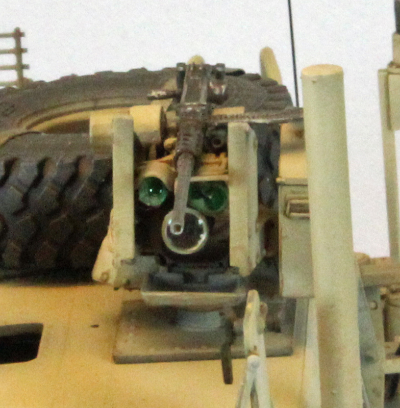
The ordinance disposal arm can be positioned in just about any position you wish. Its length exceeds the entire length of the vehicle when fully extended, and that called for a base to support everything. At the other end of the spectrum, the arm can be folded up and stowed, sliding into a starboard-side support rack on the roof. You will need to assemble the articulation simply to see how the remaining parts fit, just like with the other assemblies in the kit. Once you have it all together, though, you can cement everything in place if you wish. Bronco provides some soft black tubing to represent cabling, which you add later in step 55, but I could not find any adhesive that would work with the stuff so I replaced it with four runs of fine black wire. The entire arm assembly comes together surprisingly well, considering its complexity. The front bumper connection is relatively weak so I drilled holes in the arm and the bumper and inserted a stiff metal rod to allow me to attach and remove the arm at will. I added the small glass lens for the floodlight later.
It was here where I stopped assembly to paint and weather the vehicle using the steps listed in those sections below.
Time for 'Phase III'...
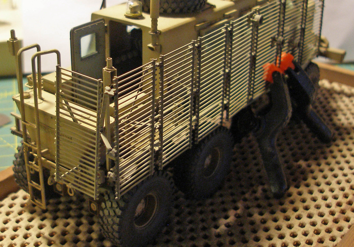
Slat / Cage Armor
What can I say? This part of the build was a challenge, so much so that if this was not a review I probably would have just completed the kit, sans armor. The armor's engineering is simply brilliant, like the rest of the kit: paper-thin plastic with zero flash and minimal (and insignificant) sprue attachment points, and everything fits perfectly. The design, however, leaves much to be desired. Bronco should be commended for their commitment to accuracy, but unfortunately it comes at the expense of build ability. Each chunk of metal is on the real vehicle is attached with nuts and bolts and screws and welds. What we get in the kit are the same chunks of metal, rendered in plastic, but without the nuts, bolts and welds.
So this tiny block of plastic is supposed to be attached to that tiny block somehow, and it's up to you-and your array of adhesives-to attach it in the right place, at the right angle, and to keep it there while it dries. In the few places where attachment points exist, they are so small and shallow that the pieces still need to be coaxed by hand through the process. For example, there are no lateral/horizontal clues as to where to place the completed side armor assembly (step 47). None of the 3 connecting brackets (M1-M3) are set at a right angle to anything; they all lean one way or the other, hence it is impossible to figure out how far forward or aft the side armor actually sits. You have to skip a few steps forward to step 54 and assemble the rear armor first. Before that dries, you need to temporarily attach it to the rear of the vehicle so that its brackets are set correctly, just to establish the rear corner of the armor in space (see images).
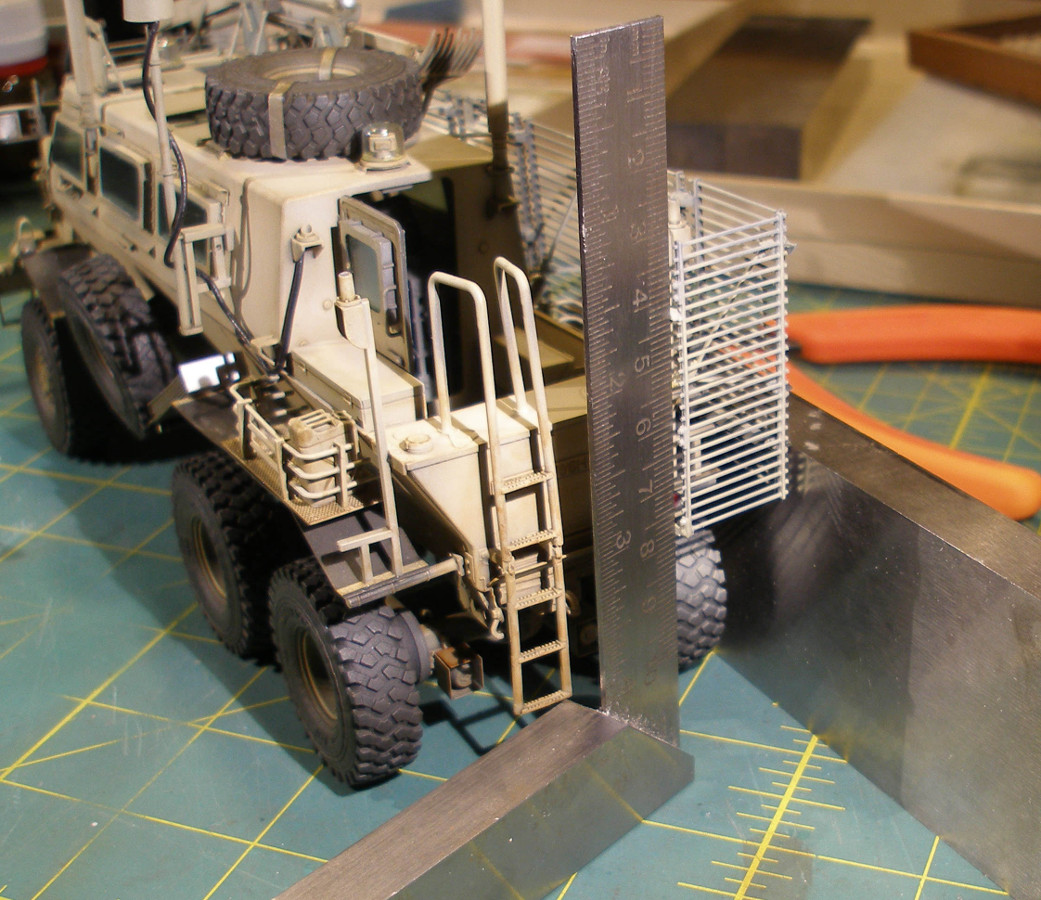
From there on, you can walk the remaining sections forward all the way to the front fender, letting each bracket dry in its proper angle as you go. I wanted to paint the armor separately so this all had to be done in such a way that I could remove the entire assembly after it was dry for painting and weathering.
Notes on assembling the sections
Looking across the instructions, I made the following notations during assembly:
Choosing which one of two types of floodlights to use was easy for me once I tried to bend PE Part P46 into shape to accept the light made for it. I tried two times but neither one came out square enough to fit between the horizontal bars of a cage section, and no extra PE is provided. So alternate part Se-1 type floodlights it is!
Look very closely at the cage armor sections. There are tiny bolts that mark the spot the attachment hardware is supposed to be placed. These bolts must be lined up with the same bolts on the next section, and so on.
I recommend you attach the floodlights AFTER you assemble each entire side, after step 47. Otherwise the side (made up of 8 sections) will not lay flat as it dries. I had to create a jig to hold the side off the surface of my workbench since my floodlights were already attached.
The p/e back plates (parts P45) will not attach to the floodlight through the cage armor as shown in the instructions. Not even close. I just glued them to the back of the cage armor section where they're supposed to be, once I attached the floodlights on the front side.
I created a jig (see images) using clamps to hold the completed side sections so that they could be attached along the top by the four cross bars (parts M16, M17x2, M31). When you glue these cross bars make sure you place them at such an angle that keeps the armor assembly evenly spaced away from the side of the vehicle.
Final assembly
Once the cage armor had a chance to dry, I attached the side mirror, robotic arm, crates, water jugs, and whip antennas. I then painted the insides of the headlight housings using Tamiya Chrome Silver before inserting the clear plastic lenses using Gator's Grip Hobby Glue, which works great for this purpose.
The Finish
Painting the Buffalo is like painting a porcupine: you can't really lay it down and you can't really hold it. After a few awkward attempts, I found that if I left off the spare tire and the gun assembly from the non-armored side I could grip the vehicle safely using my thumb and forefinger on that side. At the very end, after these assemblies were attached, I simply 'held' the vehicle using a wooden tray lined with spongy shelf-tack material to hold it in place.
The Buffalo is going to be a desert color, and rather than try and find the perfect shade, I decided to start with a fairly dark color, and bring it to life using post shading, washes and filters. I have yet to 'dial in' the mysteries of LifeColor paints and Model Master makes a paint called U.S. Army Marines Sand (2136), so I thought I'd start with that. The single scheme provided in the instructions shows a Sand color with call-outs for Mr. Hobby, Hobby Color, Humbrol and Tamiya.
(Note: I thin Model Master Paints using their own airbrush thinner. For hand-brushing I use Vallejo's own thinner for their paints. I thin all filters, washes and wet pigments with odorless Mona Lisa Paint Thinner. I use a Paasche-H single-action airbrush, #3 tip, at 20 lbs. pressure for everything.)
Interior
Fire Extinguishers: Tamiya X-7 Red and Tamiya XF-16 Flat Aluminum
Various boxes, electronic cases, posts, seat bases and seat belts: Tamiya XF-69 NATO Black
Floor and side panels: Tamiya XF-23 Light Blue + XF-25 Light Sea Grey
Inner roof: Gunze Mr. Surfacer 1000
Steering wheel & post, seats, air conditioner vents, box and case detail, dashboard control panel, center console control panel: Tamiya XF-66 Light Grey
Dashboard Console and center console: Tamiya XF-19 Sky Grey
Radios: Vallejo Model Color Yellow Olive
Windows: Alclad II Armored Glass
M2 50cal 'Ma Deuce' Machine Gun (XM153 Crow II System)
I started by hand brushing the metallic portions of the guns and the ammo belts with Testors Flat Black. This is the only time I ever use flat black model paint. Once the paint was dry, I used a silver Prismacolor artist pencil to liberally highlight the flat black and desert tan metal parts and the ammunition case. I finished by giving everything a filter using Mig Wash Brown thinned with Mona Lisa paint thinner.
Wheels
After a primer coat of Tamiya NATO Black, I painted the tire portion of the wheels using Model Master Helo Drab, and the wheel portion with Model Master U.S. Army Marines Sand, trying to keep the colors separate with careful airbrushing. Once dry, I applied a liberal filter with Mig Wash Brown, and a pin wash using thinned Mig Dark Wash, picking out the single bolt heads and seals using a fine sable brush. Next I made a wet slurry of Mig European Dust and Mig Light Dust pigments, thinned with Mona Lisa, and I hand brushed each entire wheel, front and back, and waited for the slurry to dry. I then brought the 8 wheels out onto my driveway and, using a stiff horsehair paintbrush, knocked most of the pigment off (quite messy!). I ran my finger across my forehead and vigorously rubbed the outer portion of the wheels to produce a dull shine suggesting weathered rubber.
Exterior
I built the entire vehicle up through step 42 before I stopped to paint it. I did not mask the window openings; I simply was careful with the airbrush. If there was any over spray you'd have to be a little guy sitting inside the Buffalo to notice it. I painted many of the sub-assemblies separately and attached them after the main superstructure was painted, but before the armor was added. The parts I left off and painted separately include:
All Windows
Mud guards
Step ladder
XM153 Crow II weapon system
Wheels
Roof hatches and support struts, etc.
Antenna masts
Side-mounted storage baskets
Rear door
Rear-view mirrors
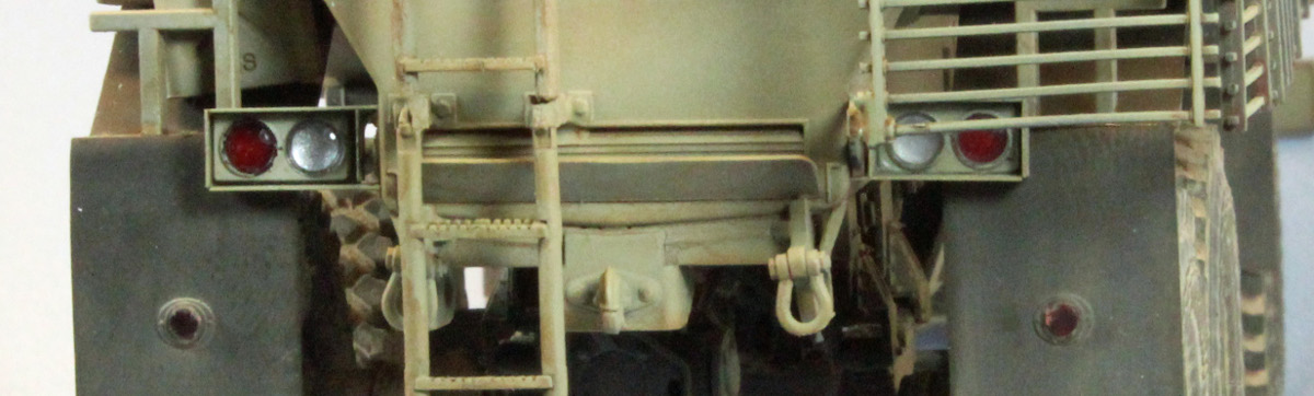
Rear tail-lights
Primer
I began started painting with a primer coat of Gunze Mr. Surfacer 1200 to cover up errant glue spots and to provide a 'bite' to the p/e parts for the subsequent layers of paint. I had to spray carefully to minimize the amount of paint that could blow into the openings, without the windows and top hatches in place.
Pre-Shade
I started by painting everything Tamiya (XF-89) NATO Black. The dark paint fills in the recesses and creates a shadow effect near the flat surface edges, adding depth for the subsequent coats to come. Again, the black paint had to go on carefully around all the openings so no paint would go inside. This was especially true around the window frames.
Base Coat
Once the paint was dry, I carefully applied a coat of Model Master U.S. Army Marines Sand (2136). I airbrushed it carefully, allowing some of the black to show along the edges, behind the wheels, underneath the protruding detail.
Post-Shade Next I applied a post-shading coat using a 1:1 mix of the above base coat paint and Model Master Insignia White, lightening up all the panels moving from the center outwards, paying special attention to the upper surfaces exposed to sunlight, and leaving what was in shadow, darker. Once this was dry, I attached everything in the list above except the whip antennas. The windows fit so well that I just had to push them into place. Nice.
Filters
Once the paint was completely dry and still 'reasonably' flat, I applied several thinned coats of MIG Wash Brown Oil Paint to the entire vehicle and all the separate assemblies, anything that was painted in desert tan and/or Helo Drab. I applied several more filters of diluted MIG Dark Rust to the muffler, but only to alter the overall color a little bit.
Wash
I applied a pin wash of MIG Dark Wash (aka Burnt Umber), thinned with Mona Lisa, to the entire surface area. I focused on the joints, cage armor and window sills. By brushing on some Mona Lisa first, the wash quickly recedes into the recesses and dark corners, providing depth to the background paint.
Streaking
Next, I dabbed on some AK Interactive Streaking Grime and DAK Streaking Grime on the vertical surfaces. I let that sit for two or three minutes and then started working it with a flat paint brush, using an up-and-down motion. The brush should be clean for this to work right, so whenever the brush got filled with wash, I dipped it in Mona Lisa, wiped it off on a paper towel, and continued. This process takes a while, but in the end you get a nice variation of an otherwise bland, single-color surface (see images). This technique works well to break up any solid color (American Olive Drab, German Grey, Desert Yellow, etc.) – any surface that needs a little help.
Metal Highlights
Once all the dusting and pigments and washes and filters were applied, it was time to lay down a little bling. I feel this step is especially important when I am working with a single-color subject. I use two products, each one producing a slightly different effect. First, I apply MIG Gun Metal dry pigment, using my finger and an artist's color sShaper that mimics the supple surface of my finger when I am working on spots where my fingers don't fit. The pigment goes on dull, but can be shined up depending on how much you work it into the (flat) surface. The second product is Gamblin Silver Oil paint. I scrape a little paint onto a business card to leach off some of the oil, and then use the color shaper to apply this brighter color to the areas that might need a little help.
Oil and Fuel Stains
The last step was to apply LifeColor Tensocrom Oil, straight from the bottle, to the areas behind the wheels and around various seals here and there, drawing the color downwards like an oil stain would look. I used AK Interactive Fuel Stains to highlight the areas on the top of the vehicle where you might find spilled fuel. Like the Oil treatment, this product dries slightly glossy to help break up the otherwise flat surface.
Conclusion
This kit is not for the faint of heart. You have to know what you're doing, you have to have a lot of patience, and you need to know how to slow down. There are a lot of "You gotta be kidding me" moments and there are times when you just have to forget the instructions and build things the way you think they should go. Many times there are no easily-defined connection points between parts. Sometimes they are absent all together. I think this is a result of prioritizing accuracy over build-ability, which is fine, but someone planning to build this kit needs to understand that. Dry fitting and methodical inspection, more than any other kit I've ever put together, is 'de rigueur' for this build. I think I spent more time planning than I spent building and painting. Each step of the build had elements that affected other steps. Each time I left the paint booth I knew I would be going back for the same colors later as new requirements unveiled themselves. It was a process. In the end, however, extraordinary effort breeds extraordinary results. The finished product is impressive and I was able to experience a real sense of accomplishment with this challenging and interesting build.
I recommend this kit for experienced modelers only. All things considered, however, the build went relatively smoothly and the result is a real head-turner. My hat is off to Bronco for taking on such an ambitious project and for producing such an amazing kit.
I would like to thank Bronco Models and Stevens International for providing this kit for review, and to Internet Modeler for giving me the opportunity to build it.