|
 |
Introduction
Hi! I’m a new Internet Modeler writer.
I consider my scale-modeling genre to be "cool shapes and colors". Since cars often fit that bill, I plan to submit varying auto-related articles, from time to time.
I’m also a bit of a sci-fi guy: but lately the only sci-fi models that have jumped out at me as “must builds” have been large, well-researched scratchbuilds (of obscure subjects); or the occasional fun kit-bash.
I must admit I’m a big fan of Gabriel Stern’s style of writing: “Lite” on text; many pics; and very positive. I will try to do something like that, from time to time ... but that will likely come about when I burn out on mega-projects (like this one!) and badly need a break. Even when I get really wordy (and I’m sure I will!), I’ll try to keep the ratio of pictures to words within an interesting range.
ABOUT THIS ARTICLE
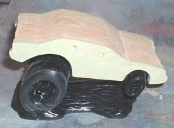
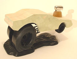
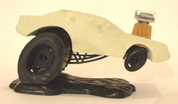
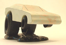
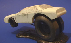
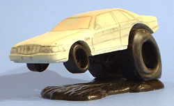
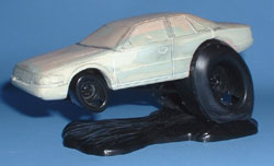
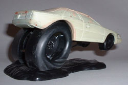
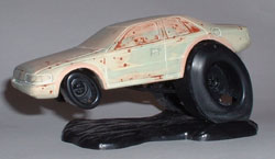
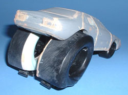
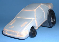
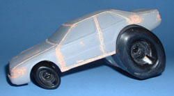
This article covers a lot of ground -- but even so, it doesn’t show a complete project, from start to finish. The reason this article ends with a model in primer is because I did not start with a kit, which was ready to assemble and paint: I started with a handful of photos of a friend’s “real life” car. From those, I built a caricature car body, totally from scratch. Fans of the Hot Rod art of folks like Bid Daddy Ed Roth, Stanley Mouse, John Detrich and others will no doubt understand what I had in mind.
I’m due for a few “Lite” articles, after this monster! So, next time, I plan to do myself a HUGE favor and simply talk about assembling and painting one or more resin copies of this model: as if it had come in a kit. (The body was made to work with the chassis, wheels, etc. of existing kits; specifically, the “Snap Draggins” series by Polar Lights.)
STEP ONE: MINDSET
|
|
My best mindset offering is this: don’t always try to do everything perfectly, in a single step. I suggest you plan to do most things in more than one step; and simply aim for a “B” or “C” letter grade, at each step in the process.
Do this math with me. Ideally, you’re shooting for 100 percent: right? (100 points out of a possible 100.) If you sit down and figure out how to get to 75% of that end goal, in your first step, that’s not bad initial progress.
Now figure out what’s left to obtain: in this case, it’s 25%. What’s 75% of that? It’s 18.75%. Okay, so take the 75% we got in the first step, and add 18.75% to that. Bingo! In two relatively easy, stress-free steps, we’re at 93.75% of our initial goal of 100%. What this means is that with two steps of “C” work, you can do “A” work. That seems counter-intuitive at first, but it makes sense. We’re just changing the rules a bit: instead of being boxed in by the idea that all “tests” are done in such a way that you only have one chance to get things right, we’re giving ourselves a few more tries. This isn’t a vague hope that magic will work: it’s a way to make progress, faster than one might think.
The main prerequisite is a willingness to be imperfect.
I feel the main difference between a beginner and an intimidating expert is whether or not the person is doing their early stumbling and learning in private, or not. (The “or not” way is much more informative to article readers!)
If you don’t mind falling down a few times on your journey, you can make excellent progress. But if you fear that first scraped knee or whatever, you’ll stay right where you are. (And hey: if you’re comfortable there, that’s okay too!)
Credit where due: the core idea behind this thinking was something I picked up from small business magazines in the late 1990’s. They called it the “80 / 20 Rule”. I’ve also seen the idea in different forms, in various other places.
As you'll soon see, I knew where I wanted to go -- but not necessarily how I would get there, exactly. (Hence the subtitle, above.) I'm not going to hide that fact, or act like I knew what I was doing. Often, I didn’t. I did have a pretty good background of helpful stuff, but a lot of my work on this model was educated guesswork and persistence, and the stubborn insistence that I would figure it out.
However, balance is an excellent thing to strive for, too! One of the things I consciously learned, from the last four months of concentrated work on this project, was to “let go” when necessary. (Like submitting a primered model!)
I think I’m going to have to try to stay inside my comfort zone, more often. Not give up on stretching my abilities; just do more “Lite” projects, that don’t require much more than sitting down and doing some fun, familiar tasks. (One mega-project to three or four easy ones, maybe?)
STEP TWO: INSPIRATION
First, I had to be inspired to do this particular project. A few factors contributed to that. I was ready to extend the knowledge I’d gained from several big projects. I had just purchased the two “Amazing Vehicular Modeler” magazine specials that the folks from “Amazing Figure Modeler” magazine had put out, back in 2004 and 2006.
I was hugely inspired by what I saw in those pages -- the fun and creativity displayed. I had to do something like that! The final straw was a friend’s birthday. (Which came and went, six weeks ago. Oops! Sorry, Will!)
STEP THREE: DONOR PARTS
While I didn't mind making a body from scratch, I didn't want to have to make every little part on this model.
The Snap Draggins series are a popular way to obtain cool-looking, pre-made ‘toon (cartoon) wheels and tires; plus other “accessories” a person may want, when kit-bashing cartoon cars. The important thing here is perceived scale: if you're going to use kit parts, that locks you into a certain size range. I didn't mind that: I welcomed having a model more or less in scale with the other Snap Draggins kits. (Formerly Drag Toons resin kits; before Polar Lights made an agreement with The Good Stuff to translate the six models in the series into injected plastic form.)
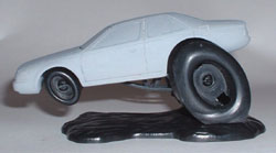
The car I used as my donor was the “Manglia” -- but that’s mainly due to it not running away fast enough. (Actually, because I had cut up the body for another project.) Any of the five other cars would have also been a good choice: a lot of the parts are either identical or very similar, so use any kit you can cheaply / easily obtain. As with any kit-bash effort, all six cars will require some adaptation to work with your particular project. The notable areas are likely to be the wheelbase (front-to-back measurement, at the wheel centerline); maybe tire spacing (side to side); possibly the “wheelie” angle; etc. But there’s plenty to like about these kits -- either box stock, or as donors.
STEP FOUR: PHOTOS (REFERENCE MATERIALS)
Over the last few years, I have become comfortable with "orthographic projections" -- blueprints, in short. I had recently gained experience with converting 2D data into both 2D and 3D form. Based on that mindset, I made this theoretical observation: the main thing you have to get right, to make a car model look like the real thing, are the outlines and proportions of the profile (side) view.
The rest matters too, of course: but not as much. I based this on the perhaps "pushing it" idea that from all other views, just about every car is a modified rectangle. From all other views, you’re essentially starting with a pure block (of a certain set of proportions). You’re then “just” cutting or sanding off a bit: usually around the corners.
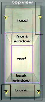
This is where that “80 / 20 Rule” comes into play, in this project. I figured I had a starting point, by focusing on the profile view first; and then “cutting off” portions of the other views, little by little. As you’ll see in the pictures, the form became a very blocky version of what I wanted: a silhouette that mostly worked, when seen from a straight-on view; but that wasn’t satisfying otherwise.
At that point, I figured I could start to sort of blend or round off any edges where the various straight-on views would meet, in a blocky fashion. And that worked out well.
Side notes: That's the official reason. It’s true, but it’s not the whole story. When I visited my friend at his home (200 miles away) I had run out of "digital film" for my trusty (borrowed: thanks, Clarinsky!) Fuji FinePix 2600Z digital camera. (A mere 2.0 megapixels! Ha! And wait till you find out I'm dumping the raw images onto a 500mhz e-Machines PC that was designed for, and still runs on, “Windows 98”. And I crop and adjust things with Paint Shop Pro 5 -- a program that's about as old as the PC I use.)
Bottomline: thanks to other vacation pics I would have been in big-time trouble for “erasing,” I had just enough memory to get shots of the real car's sides; the front; and the back. And that would have to do, as far as my early references went.
I’ll say this: there’s no way in heck I would have thought that four (three, really) views would have been enough, had I not stubbornly stumbled through my three-foot-long “Dark Star” scratchbuilding project, one tiny step at a time. It was on that project that I learned to “blend” the views. A lot of things (contours) that drove me batty, trying to figure out in a 2D form, made perfect sense when I went as far as I could with a 3D model using straight-on views; and then, when I could go no further that way, learned to “just wing it” with a belt or hand sander, on transitions.
I found that doing so matched perfectly with references; the reason being, you faced problems the original builder also faced; and with a bit of luck, you did what they did.
The funny thing is: this sort of stuff used to be commonly known, and no big deal. The early Egyptians used similar techniques to build huge statues. Boy Scouts were expected to earn Merit Badges by using those concepts to whittle wood projects. How soon a computerized society forgets!?
STEP FIVE: INTENTIONAL DISTORTIONS
At this point I was still working in 2D mode: I was thinking ahead to 3D, but wasn’t to that point yet.
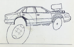
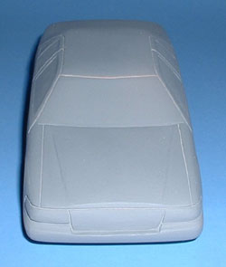
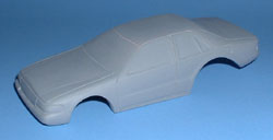
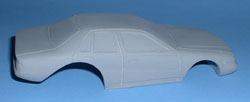
My next big step was to decide how much I should distort the outlines and proportions of the real-life Cadillac STS vehicle; and where; and how. At project’s end, it had to be recognizable to viewers as an STS; while being a cartoon; and also being in scale with the kit parts I’d be using.
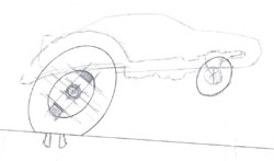
It took much thought, but I finally worked out the best way for me to leave most of the 2D “real thing” images alone, while distorting only the areas I wanted to. The answer?
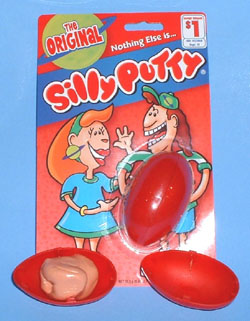
“Silly Putty"!
Sometimes, the best ideas are the silliest. Err, simplest.
A pro (and friend and mentor) whom I showed the process to dubbed it "ancient morph technology". That’s what it is -- a cheap, no-computer-necessary way to alter 2D drawings.
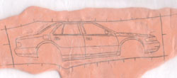
My initial hope was that the material would pick up all of the inkjet ink on a printout. No such luck. Nothing at all transferred over to the Silly Putty. A bit of playing with it fixed that: I just had to trace the outlines first, with a mechanical pencil. The graphite does transfer over.
Study the pictures: there’s a lot of good info there.
To supplement that (and refresh my own memory later!) I’ll hit some nifty, helpful highlights about what I learned.
Because I was going to use kit parts, I was locked into a certain final size. This did not mean I had to work in 1:1 “final model” scale, however. It just meant I had to keep track of whatever ratios I was printing test prints at, as I went. (Writing it down on each test print worked fine.) In this way, I could work at two or three times the size of the model, while I was tracing things. That helped a lot, in terms of following each line’s subtle curves, well.
Eliminate distracting backgrounds by cutting your printout with high quality, precise scissors. (Medical surgery type; or decal, or whatever.) Because the model would have mis-proportioned cartoon wheels, I cut the real ones off.
Tracing subtle lighting differences is hard. Trace things like door edges or “character lines,” directly onto the photo, using a high-contrast pen which won’t smear later.
Once you have a 2D line drawing traced onto tracing paper, you can re-trace that in (small diameter) pencil; and then place some rolled-out / flattened Silly Putty on top of that drawing; and apply gentle pressure to “copy” it.
Wax paper is a good thing to have handy. I used it on the bottom of the Silly Putty, when rolling it flat; and also on the top, after “picking up” the pencil’s graphite. I didn’t want it to stick to the bed of my PC’s scanner, when I plopped it down there, to scan in a print-able version.
Experiment with stretching Silly Putty, to get a good idea of how quickly / smoothly it stretches. You may mess up a time or six (as I did) enroute to getting a firm handle on how to “pull” only selected areas. My early attempts all had way too much unintended distortion.
If you study the pictures, the rectangle will show areas that were stretched; and there are little marks or indents in various places, indicating areas I had to "push back". (I added the rectangle via computer, after scanning in the 2D tracing; but it could easily be added by hand.)
Once I had calibrated my wrists and fingers properly, via practice, and learned the rectangle trick, the intentional stretching worked out pretty well. However, I did make a number of small corrections (or “I changed my mind”) as I went. To do this, I used a small screwdriver’s tip, to “push” small local areas back, here or there.
The end goal of all this is to end up with a 2D drawing that you can reduce or enlarge in some way. I used a PC and a scanner and an inkjet printer. Another way would be to go to some place that offers photocopying services for a fee.
STEP SIX: MATCHING PLANNED PARTS TO KIT PARTS
As noted before, I planned to use kit parts for everything but the car’s body. That means my planned 3D body, when it was actually made, had to be sized to match the kit parts.
The easy way to work out that problem, in the 2D stages of things, is just to take one transparency film (that has a 1:1 tracing of the kit wheels, chassis, or whatever parts you will be using) and to lay it over a paper printout of the body style you will be using.
If things don’t match up, you’ll quickly see it. Reduce or enlarge the printout of the car body (since that’s the part that doesn’t exist yet; and is therefore the one most subject to change). Then try again. Eventually, the two 2D drawings will match up. When they do, line them up well and tape them together; then re-copy this new, combined image.
STEP SEVEN: UNINTENTIONAL DISTORTIONS
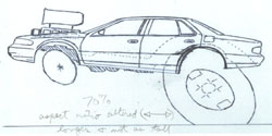
I made a happy boo-boo (mistake) during one or more of the resizing steps, of my “final” combined 2D drawings.
Basically, I wasn't paying enough attention. I told my PC to print out the test images at a certain size. But I did not check the “print preview” first, before I printed. As it turns out, an unintentional distortion was added. This was an attempt to be “user friendly,” on the PC’s part: and it did turn out that way, because I liked one of the new images better than what I’d come up with. (Implying there were several different PC-distorted versions. Yup!)
The mistake was this: I was working in 2D at a larger scale than the real 3D model. (Probably 1.33 to 1, on up to 2:1.)
Even the first printouts were close to being the full size of the sheet of paper. For the record, I was leaving the data (scanned image) that represented the picture totally alone: that, I was not changing in any way. But each new printout got printed at a different size.
At some point, I wasn’t paying enough attention, and I told the PC to print out an image that would have gone “off the page”. The PC basically said “Stupid human!” and helped me out by shrinking part of the image, to fit onto the page. (This is a program-by-program thing: not a universal PC trait.) Note that I said “part of the image”. What I mean is, the PC had plenty of room (for example) from top to bottom; but from side to side, part of the image would not fit well. So, in this example, it would have shrunk the image from side-to-side; while leaving the top-to-bottom alone. (You can also do this on purpose, in some of the more powerful painting programs. Look for the “aspect ratio” numbers, within your program’s print menus.)
I really had no excuse for not noticing this, right away. My artistic training should have “calibrated my eyes” better than that. But I was in a hurry, and it happened. And once I had choices in front of me, I was glad it did.
I found I liked the altered looks seen in certain of the printouts -- the new aspect ratio -- better than the way I had originally "drawn" things. To use that as the new way from then on, I scanned the coolest-looking printout in, and saved that data. I made all new printouts from that.
STEP EIGHT: STEPS WE’LL PRETEND DIDN’T HAPPEN
Initial attempts to make a 3d car body were -- how to put it -- “less than successful”. (They sucked.) Not so much on an absolute basis; more on a “thinking ahead” basis.
What I mean is, I planned to make more cartoon models of other real life vehicles. That being the case, I wanted to get into good, effective, efficient habits as early as I could. And I could see those two early methods were going to cause so many needless steps in the later stages of the game (to keep me in my comfort zone, earlier on), that I gave up on them within a week or so. And then floundered, looking for some better method to replace them with. (I described all of that in the first draft of this text. I later killed two pages of that, for reasons of length.)
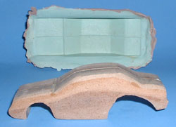
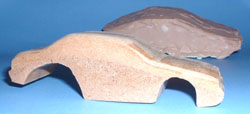
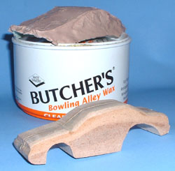
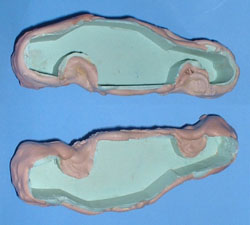
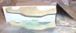
Short story is: I tried to make a body out of MDF “wood” (which I think of as “Poor Man’s Renshape”). I made hard molds of that, using auto body fillers. I planned to make filler castings from those, for use as intermediate masters ... but it quickly became way too inefficient to pursue.
You’ll see the initial attempts at this, in the photos. Of note: the hard molds I made (after waxing the MDF “wood” body up, so nothing would stick to it) are made of “Glaze Coat” as a surface layer; and thicker Bondo brand filler as a backing layer. Also: the rounded edges of the MDF body happened after I made the upper mold piece and the two hard side molds. (I think I figured I’d get some “edge blending” practice in, using the now-useless rough MDF master.)
STEP NINE: PROFILE TEMPLATE
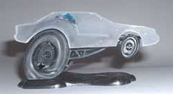
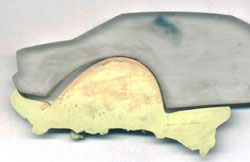
My third attempt at coming up with an efficient methodology for building future, cartoon-ized auto bodies was much more successful. Simply put: I traced my final “1:1 model size” printout onto a scrap of Lexan sheet, and I cut it out. A handheld household-type jig saw, initially; then cleaned the edges up on a one-inch Dremel brand #1630 belt sander.
The blue blob on back of the Lexan is dyed baking soda. I have a whole article I'll do on that subject; but the short story is, baking soda has lots of water molecules in or on it; and water molecules "set" or harden my favorite (water-thin) type of super glue, in seconds. It's an old trick. What's new about it is that I've dyed the baking soda, before use, using inkjet refill ink. By doing that, I can easily see if I have over- or under-glued; and I can see when I'm about to over-sand, as well. (It normally hardens in a clear state: which has major limitations. The dye removes the limitations: making it nearly akin to magic!)
Some of you may have seen a brief version of that idea: it ran as “Colored Filler” in the Oct 2007 issue of Kalmbach’s “Scale Auto” magazine, as their “Tip of the Month”.
STEP TEN: “BONDO” MOLDS AND CASTINGS
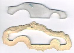
I used Lexan for my template because it comes in flat, 2D sheets of a consistent thickness. This meant I could cut out one side/profile piece; wax it well; then make a Bondo mold of the outline of that piece. (Making a 2D negative or "hole," using a positive 2D form.) Then I'd make two flat, identical Bondo castings, inside that Bondo mold. (Making a positive form, within a negative / "hole".) This would fix the symmetry problems I had earlier, between the two sides. (Which I described more fully in the two pages I killed.)
For the record: the term “Bondo mold” is generically used by professional scale modelers; and has been, forever. It isn’t really correct. It’s more of a shorthand term, used to describe hard molds made using two-part, catalyzed auto body fillers. The word “Bondo” is actually the name of the company that makes one of the most common of those fillers.
One related problem is that some kit builders call the red, air-dry putty made by Bondo, “Bondo”; and others call their pinkish-grey, two-part filler “Bondo”. You have to read articles by either folks very carefully, to figure out by context which of those two they are really talking about. (And guys like me complicate it further, by referring to competing company’s products as being “Bondo-like”.)
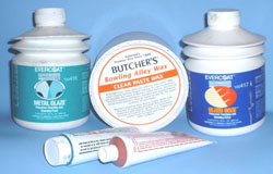
I do use real “Bondo” brand fillers, from time to time – mostly on my larger projects. On this project, I used the Evercoat company’s “Glaze Coat” product, exclusively.
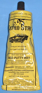
Almost exclusively: all the way up to the very last stages. I then used the lacquer-based “Nitro-Stan 9001” touch-up putty for pinholes or minor details. (You can mail order it through Coast Airbrush in Anaheim, California.)
I stopped using hobby putties nearly ten years ago. I don’t plan to ever go back. Most air dry putties aren’t worth a spit, in my humble opinion, once you climb the required learning curve on using two-part, catalyzed materials; and become comfortable with their “habits”.
I regret that space limits won’t let me go as ballistic as I could, in talking about “icing”. See the pics for two great products I enthusiastically recommend for any sort of detailed filling or contouring work. Both are by Evercoat. (My local CarQuest store special-orders Evercoat’s line.)
The “Butcher’s Bowling Alley Wax” is a fantastic product, but it isn’t by Evercoat. (I got mine through eBay.) It’s the only wax I’ve tried that will keep Bondo-like goop from sticking to even a porous MDF surface. One layer of this stuff is usually enough; several layers of common car waxes may still not work. (It also cleans off of surfaces without much hassle -- a major consideration for glue or paint.)
A big thanks to David Merriman for turning me on to most of those very cool, very superior products. (Pass it on!)
Quick notes on using Bondo-like, two-part products:
These products cure in four stages: like peanut butter (before mixing, and soon after); same idea but starting to lose its aggressive tackiness; a hard wax (that temporarily loses some of its adhesive powers to other materials -- so go easy on harshly shaping it!); and finally, rock hard.
Most of this happens in mere minutes!
If you know there are “stages” and what they are, then it’s fantastic stuff that works like magic. (If you don’t know about that, it may seem like some sort of not-good magic!)
To mix them: mix about 1 part cream hardener to 16 parts of the stuff from the can or squeeze bottle. Stir until it’s all a consistent color. I use an old phone book as a cheap mixing palette, and craft (Popsicle) sticks as mixers. In a case where super-tiny amounts are involved -- like filling small seams on a kit -- a toothpick is a fine mixing tool. (What constitutes a big or small amount may be relative!)
Cream hardeners come in different colors. Red is the most common; blue is harder to find; and good luck on finding the white! (It’s an “Experts Only” thing.) Why different colors? So you can tell where each layer starts and ends, as you apply more of it. Note that Glaze Coat, which starts out as a yellowish color before mixing, becomes green when mixed with the blue hardener. It turns a reddish-yellow with the red. (The white hardener doesn’t change the color of the filler. You get no visual clue as to when it is mixed well.) Mix red and blue, if you need another color.
STEP ELEVEN: SCREEDING
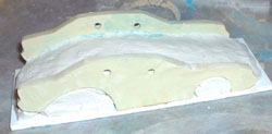
I used the “dyed baking soda and super glue” trick to lightly tack-glue the profile-shaped side-piece castings to a sturdy sheet of ordinary styrene plastic. The idea was to secure them, temporarily -- aligned well to one another -- and then to somehow add a shaped, solid roof between them.
Enter a process called “screeding”.
David D. Merriman III is one of my all-time favorite scale modelers. For those who don’t know of him, he’s a pro who mostly builds R/C submarines and sci-fi vehicle models. He wrote an excellent, very highly recommended article about the “screeding” technique in the Feb 2002 issue of “Fine Scale Modeler” magazine. (Many FSM back issues are still easily available, through Kalmbach’s web site.)
It’s a technique David has taken to artistic heights; as you’ll see in the many awesome “how to’s” on his site
Screeding, in its simplest form, entails dragging a flat device (like a wooden 2-by-4) across the top of two guiding walls: with the object of smoothing out something that has been roughly applied, between them. One example: spreading out and leveling wet concrete that was dumped into a crude wooden form in the shape of a section of a sidewalk.
That’s basically what I was doing. Picture fresh blobs of just-mixed, very thin-consistency, high-grade auto body “finishing and blending putty” being slopped on, over the clay and between the two “Bondo castings” I’d made of the sides of the car. (They generically call that stuff icing, by the way. Once you’ve used it, you’ll know why: it’s that smooth and fine!) Add a metal ruler, covered in masking tape to make clean up easier, and you have the picture.
Part of the reason this all worked is that all Bondo-like products stick like crazy. They’d have to, to stick to the sides of a real automobile, despite all the abuse that the real things go through! (Dings in parking lots; people leaning on body panels; heat expansion; severe winters…) If it will stick to a real car’s bodywork, it will stick to itself. I often use that principle to good advantage. (On my big MDF models, I use Bondo’s filler like fast-acting glue, to laminate “Bread and Butter” MDF slices together.)
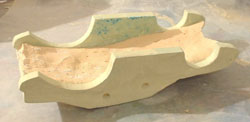
Study the pictures, closely. Notice I have clay built up to a certain point, between the walls. (And I went farther with it, later.) This is partly to make a positive form; which would result in a negative (hollow) space under the roof, when I was done. That in turn was done to conserve on the Glaze Coat material; and so I could test-fit the body over the kit’s chassis and wheel parts, at intervals.
I had originally drilled holes as alignment guides, but the idea was abandoned and replaced with a simple X-acto right triangle, to keep the two sides vertical and parallel.
Note the datum line I drew on the sheet plastic, near one corner of the wheelwells. That also helped align things.
From other pics, note that I did my screeding in stages. I did only the upper surfaces, first. Other areas were too hard to reach, while the side “walls” were still tacked to the plastic “floor” piece. I waited for the newly one-piece body to harden enough; then broke the tack-glued bonds that lightly held the sides on the sheet plastic. I then removed all of the clay, and washed the body parts off with soap and water, as best I could. (To make sure adhesion wasn’t compromised later). I re-applied more clay, in certain areas; then screeded on the front and back bumper areas.
STEP TWELVE: CONTOURING WORK
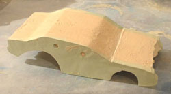
At this point I had a hollow, blocky-looking thing that needed to be less blocky. From hereon in, what I did was more or less a form of whittling. Eyeball things; find a high spot; sand it off. (And there’s no reason your model can’t be made of something like Balsa wood, if you prefer.)
As I said before, this cartoon car body was made entirely from Evercoat’s Glaze Coat. Why is that? Whenever you have layers of different materials, they will all sand and cut differently. You may end up sanding down one layer faster than another, accidentally. By using a single substrate material, I eliminated many problems.
As previously described, the model-to-be was in silhouette form only, at this point. It's almost as if I had glued 2D drawings (orthographic projections) onto the sides of a solid block, and then cut away all that I would obviously not need, from each of the views. (Well, mostly from the side view, at this point: not from the other views yet.)
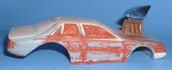
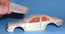
Ninety percent of the rough cutting, as it were, was done with sanding sticks. I don’t buy mine at hobby shops or by mail order. Whenever I’m in Pueblo, Colorado -- the next big town beyond this gorgeous but very remote area, which has many stores -- I go visit Sally Beauty supply, and stock up. They know me by heart now, and are friendly as can be. Their prices and selection are fantastic.
Two exceptions, on what I used to sand stuff down: for the initial rough cut on the window areas, I cheated and used a one-inch-wide sanding belt, on a Dremel brand belt sander. Towards the end, when I was doing fine detailing work, I made my own little custom sanding tools. (Something new-to-me, that I’m happy to have added to my bag of tricks!)
Side note -- the universe feels sorry for me:
After I had the sides, rear and front silhouettes worked out to my satisfaction, then it was a matter of trying to figure out what the "edge blends" were, on the real thing.
I hit many “scary new territory” panic points, on this project. This was one of them. Yes, it is a cartoon car ... but I’m a guy who wants even his cartoons to be based on the real thing; so they’ll be recognizable. And early on, I had no way to see what the 3D contours of the real thing were, without driving 400 miles round-trip to go see my buddy’s car in person. “Sometimes, the best thing to do is something”. In part what I meant by that is that it’s often necessary to do something, right now (even if it’s wrong), so you can better visualize what the next steps must be.
Just about the time I was worrying that I was going to hit a “need more information” brick wall, something incredibly cool happened, out of the blue: a friend of a friend came by to visit. And she drove a car that was very similar to my friend’s car: only four model years of difference between them. I got a quick okay from her (thanks, Lila!) and ran outside with my camera. I even had enough time, after taking sixty-some pics to add to my very thin stack of early references, to take the model itself outside and to sand it down by eye, to match the hard-to-figure areas.
A major tip -- one which would not have occurred to me if I hadn’t hit that “you can’t go any farther now, with the references you have” wall: doors and trunk lids have edges that describe, almost perfectly, the cross section of the vehicle. Shoot edge-on pics of any part of a vehicle that will open! You’ll be glad you did, during contouring work.
STEP THIRTEEN: TEXTURES AND DETAILING
Next up: things like panel lines, wheel arches, recessed side window areas, etc. Short story is: I ain’t done yet.
I got lazy and eye-balled most of that. Some of it worked out fine;
other areas, not so good. Much of it has to be massively reworked, straightened,
or just plain corrected.
And it’s Deadline Time. So ... all that will have to wait!
Part of the reason I’m not done yet, is that contouring is a matter of getting large-ish areas worked out, roughly. You hit diminishing returns when you get to this stage: it takes far longer to detail any given square inch, properly.
Tools were one problem. While big sanding sticks worked like a charm for contouring, they aren’t adequate to this reduced-size task. About a week ago I experimented with a tip I saw in the Sep. 1998 issue of Internet Modeler by Art Anderson. My version of it is to use gap-filling (green bottle) Zap CA glue, along with “Cheez-It” cracker box cardboard and a rescued, good portion of an otherwise worn-out sanding stick. (I have dozens of those!) Why am I excited about it? Try it yourself, and you’ll quickly see!
STEP FOURTEEN: MOLDING AND CASTING
All along, it was my plan to make a mold of this body and to cast up at least a few copies of it. Not to sell: just to have a few extra copies of it for friends and myself. (And I’d scream if the one-and-only got lost in the mails!) I need more time to experiment with all of my current work on “mother and glove” molds; and “slush casting”. For now, I’ll refer you to some of the places I learned about that:
A wealth of great “mother-and-glove mold” info can be had in Merriman’s (somewhat infamous) “Dove” scratchbuilding article (more like book) series.
You can also find hours of truly excellent info on DVD’s #5 and #7 of the CultTVman “Fantastic Modeling” series:
A pro by the name of E. James Small wrote two interesting articles that involve casting info. See either the Nov 2002 issue of Fine Scale Modeler (for his “Seeker” article) or his article in the #57 issue of Modeler’s Resource. (No longer available through MR’s web site: sorry!) The FSM article includes the best “slush casting” explanation I’ve run across; plus good tips on transparent castings.
CONCLUSION
I’m somewhat disappointed in myself, that I didn’t get this whole project wrapped up in time for this month’s deadline. I’m probably being too hard on myself, however. To get this much done (and written up!) in only four months, with multiple other hobby projects going on ... not too shabby!?
I’ll end with this: “Outlines and proportions; contours;
texture; final paint”. That’s my five-part theory of what
any model building project amounts to. I did the first three-and-a-half
of those, already. I just have to work on the final body detailing work;
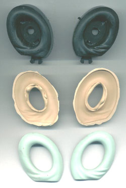
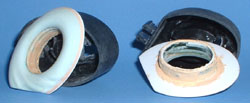
fine-tune things like the tire inserts I’m working on; assemble,
and paint it. So, most of the hard work is over with. I do want to take
my time on the casting process, and the paint jobs; so I will probably
skip next month’s issue, and finish this project off, after that.
Next month: dyed baking soda tricks!

