Roden 1/48th Fokker D-VII Alb (early)
|
 |
Construction
For history on the plane see the inbox review from last months IM.
First a short apology, Ive been trying, with much difficulty, to use my old Sony Mavica camera for these reviews. Im suffering middle-age syndrome in that some of the stuff I thought was new, is old and bordering on obsolete. So I apologize for the dark grainy shots in this article taken with the old Sony, and I apologize for the detailed out of focus pictures taken with my new 5 megapixel Nikon. Maybe by the next article Ill have learned how to properly use the new camera!
The subject of this review is Rodens
kit number 421, a 1/48 rendition of the Fokker D-VII Alb (early). This
follows on the heels of kit #415 the Fokker D-VII, early version, #417
the Fokker D-VIIf, and #420 the Fokker D-VII OAW (early). Still in the
works at Roden are kit #418 the Fokker D-VII OAW (mid) and kit #424 the
Fokker D-VII  Alb
(late).
Alb
(late).
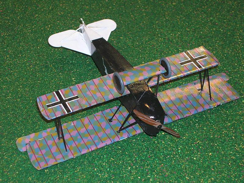
Decals are provided for four relatively colorful aircraft, complete with upper and lower lozenge and lavender rib tapes. The four aircraft are Ltn August Hartmanns OD and yellow aircraft with a Witch riding a broom on the sides; a red and white striped aircraft from Jasta 43; Ltn, RF Jakobs, green black and white aircraft with a ¼ moon on the side, and the box art black and aircraft of Ltn. Carl Degelow, featuring a large white stag on the sides. Ive chosen to do an OOB build of the aircraft on the box cover.
Just for the record, I try to build
all reviews straight from the box. No aftermarket decals or parts. I want
you to see what the basic kit provides; however on this kit I wanted to
try something new. On the full scale aircraft the dyes or coloring in
lozenge fabric did not fully penetrate the fabric. So the 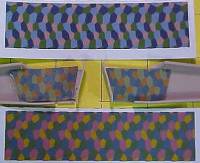 inside
of a lozenge covered airplane has a little of the white fabric showing,
and the pattern is reversed from the outside. To replicate this on this
plane I used Americal/Gryphon #109 Four-color Lozenge, Top, Interior/Reversed.
It is a little darker than the lozenge that came with the kit. But because
the exterior of the plane will be painted black, it makes sense that this
will work. However, if you want to stick to the OOB plan, there is enough
of the Roden upper lozenge to finish the inside with the kit decals, if
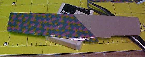
you are so inclined. Heres a shot of the Roden decals above and below,
and the Americal decals cut to fit the interior.
inside
of a lozenge covered airplane has a little of the white fabric showing,
and the pattern is reversed from the outside. To replicate this on this
plane I used Americal/Gryphon #109 Four-color Lozenge, Top, Interior/Reversed.
It is a little darker than the lozenge that came with the kit. But because
the exterior of the plane will be painted black, it makes sense that this
will work. However, if you want to stick to the OOB plan, there is enough
of the Roden upper lozenge to finish the inside with the kit decals, if
you are so inclined. Heres a shot of the Roden decals above and below,
and the Americal decals cut to fit the interior.

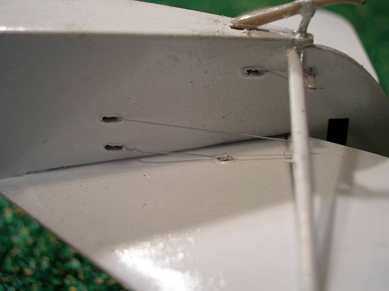
On to building: wait for it NO! I DID NOT start construction with the interior!!! In this case I started with the wings and decaling. There are lots of lozenge sections followed by rib tapes to do on this airplane and I wanted the decals good and dry when I needed to handle the wings. And, as stated above, I also wanted to do the inside of the fuselage with interior lozenge.
 To
aid in getting the lozenge decals to lie down, I first gave the upper
and lower wings and the interior of the fuselage several coats of rattle
can clear gloss lacquer, enough to put down a good shine, not mirror-like,
but enough to give the decals something to stick to. I tried to use Micro
Sol decal solvent because it is readily available, and for the flat areas
with little detail, it was adequate to pull down the Roden decals. In
trouble areas with tall or sharp bumps I resorted to a very "hot"
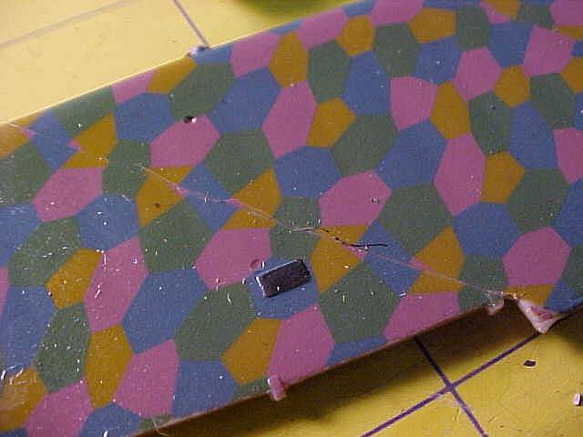
decal setting solution called CHAMP decal setting solution. You can see
its effect in this shot of the finished wing showing an errant pet hair
outlined under the decal!
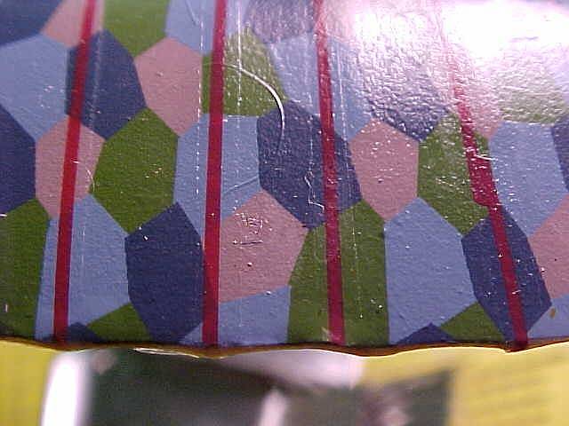
To
aid in getting the lozenge decals to lie down, I first gave the upper
and lower wings and the interior of the fuselage several coats of rattle
can clear gloss lacquer, enough to put down a good shine, not mirror-like,
but enough to give the decals something to stick to. I tried to use Micro
Sol decal solvent because it is readily available, and for the flat areas
with little detail, it was adequate to pull down the Roden decals. In
trouble areas with tall or sharp bumps I resorted to a very "hot"
decal setting solution called CHAMP decal setting solution. You can see
its effect in this shot of the finished wing showing an errant pet hair
outlined under the decal!
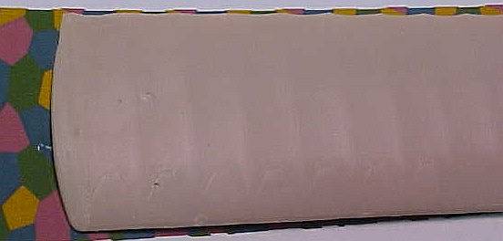
The next step in decaling this was to
first see if the lower wings could be covered with one piece of  lozenge,
and as you can see by the picture, this is doable.
lozenge,
and as you can see by the picture, this is doable.
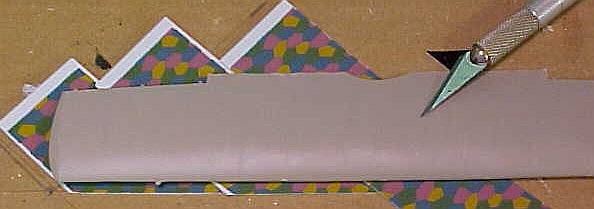
Now, because the Roden decal material is wide enough for the lower wing its not wide enough for the top. A splice was called for so I decided to try for a scale-like application. So the lower and upper lozenge for the upper wing were cut into strips on a 45-degree bias to replicate the full-scale installation. The decal material was cut and applied oversize. After it began to set the front and rear edges were cut off with a new, sharp #11 blade.
 |
 |
 |
|
This was followed by the kit-supplied rib tapes, and lastly, the national marking decals were applied and allowed to dry for several days. WARNING! The Roden-supplied rib tapes are not individual. They are a bunch of stripes on one big decal. I took the time to cut through the decal carrier between each of the stripes before they got their first water dip. I guess you dont have to ask how I figured this out. Just be aware that Roden kindly supplies more than enough rib tapes.
While waiting on the clear paint and decals, work commenced on the little bits and cleaning the stumps off of the flight controls after they were removed from the sprues. I didnt spend a lot of time on these items which I later found out was a mistake. As I found out a couple of months ago while building a Sopwith 1-1/2 Strutter, Roden parts look great on the sprue but occasionally they dont quite match up were they belong. In this case, it takes a couple of minutes of work to get the ailerons to fit on the hinge points. Also the horizontal stabilizer and the elevator have significant mismatch at the elevator balances. So take your time in the beginning, before you paint, to get all of these items sanded or filed to fit.
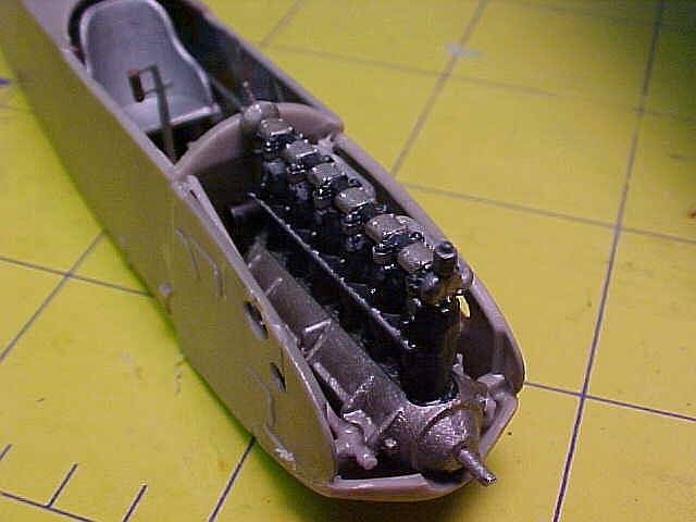
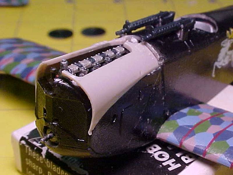
 The
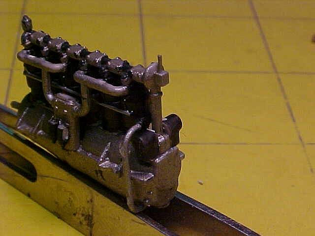
engine is a jewel unto itself, just a few parts and very little flash.
There are two tall ejector towers on the back of the cylinders that need
attention, and the front of the valve assembly is molded into the RH side
of the engine, it and the top of the LH side of the engine that fits below
it both need a little trimming to allow both parts to line up properly.
Once that is done, you can glue the case and cylinders together. An additional
potential stumbling block is at the back end of the engine. On my example,
the backsides of the magnetos had a quite a bit of flash on them. This
made them look as if they touched back-to-back on the centerline. When
I attempted to install part # 7V, the cam drive and machine gun interrupter
housing, I found this was not the case. A quick search of the photo references
on the WW-I modeling page clearly showed the gap between the magnetos
and part #7V fitting in this gap. So trim away this flash if it is on
your engine.
The
engine is a jewel unto itself, just a few parts and very little flash.
There are two tall ejector towers on the back of the cylinders that need
attention, and the front of the valve assembly is molded into the RH side
of the engine, it and the top of the LH side of the engine that fits below
it both need a little trimming to allow both parts to line up properly.
Once that is done, you can glue the case and cylinders together. An additional
potential stumbling block is at the back end of the engine. On my example,
the backsides of the magnetos had a quite a bit of flash on them. This
made them look as if they touched back-to-back on the centerline. When
I attempted to install part # 7V, the cam drive and machine gun interrupter
housing, I found this was not the case. A quick search of the photo references
on the WW-I modeling page clearly showed the gap between the magnetos
and part #7V fitting in this gap. So trim away this flash if it is on
your engine.
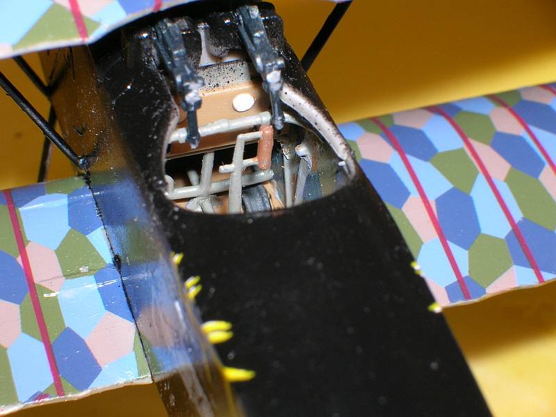
We finally move on to the interior by gluing the fuel tank together followed by the cockpit components. This is where I found the only actual error in the kit instructions. The fuel tank filler tubes part #6C and #11B are cross-labeled. #6C is the tall one and #11B is the short one, opposite of what is shown on step 2.
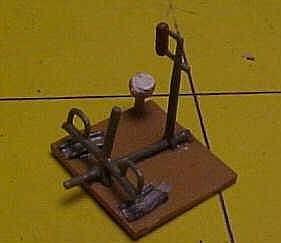 The
floor and instrument board first getting a coat of wood brown paint. The
seat was painted all aluminum, with a black leather seat. All other controls
and interior metal parts were painted with WW-II vintage RLM 02 gray.
Note that there are holes in the base of the rudder pedal assembly #31B
and the joystick #32B. Open these holes to allow the aileron torque tube
#15B to pass through both components. On my kit I also cut the locating
pin off the bottom of the control stick, as it did not line up with the
hole in the floorboard once the stick was on the torque tube. Also note
that my carpet gnomes in my shop stole the auxiliary throttle levers,
part #23B right off my tweezers as I was attempting to install it.
The
floor and instrument board first getting a coat of wood brown paint. The
seat was painted all aluminum, with a black leather seat. All other controls
and interior metal parts were painted with WW-II vintage RLM 02 gray.
Note that there are holes in the base of the rudder pedal assembly #31B
and the joystick #32B. Open these holes to allow the aileron torque tube
#15B to pass through both components. On my kit I also cut the locating
pin off the bottom of the control stick, as it did not line up with the
hole in the floorboard once the stick was on the torque tube. Also note
that my carpet gnomes in my shop stole the auxiliary throttle levers,
part #23B right off my tweezers as I was attempting to install it.
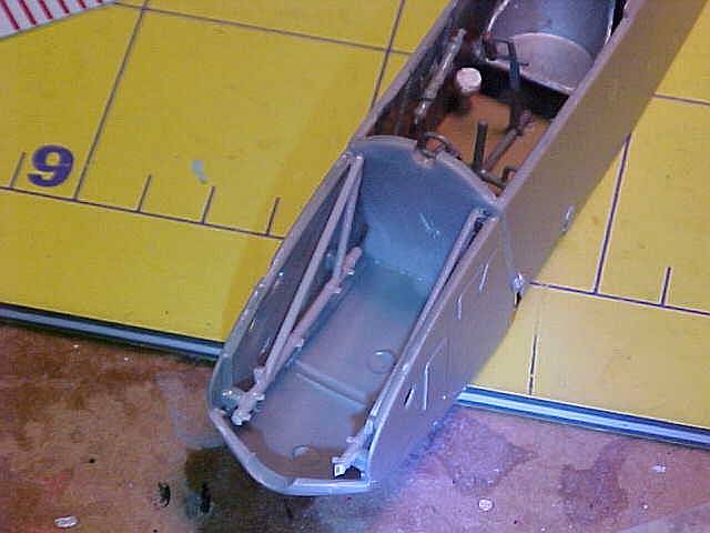
Fuselage assembly offers a bit of
a challenge in that there are no locator pins. This chore is 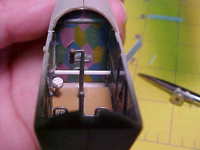 compounded
by the need to line up the floor, the aft cockpit close out panel, and
seat with the other side. My solution was to install the close out panel
on one side and take my best shot at getting it perpendicular to the fuselage
seam. Then I glued the bottom edge of the fuselage together. This allowed
enough give in the fuselage top to slide all of the interior components
down into place. This also revealed that the molded pins on the fuselage
side, which are supposed to support the seat, are too short. The seat
will neatly and cleanly fall right between them. I added a strip of plastic
rod just above them and glued the seat to this.
compounded
by the need to line up the floor, the aft cockpit close out panel, and
seat with the other side. My solution was to install the close out panel
on one side and take my best shot at getting it perpendicular to the fuselage
seam. Then I glued the bottom edge of the fuselage together. This allowed
enough give in the fuselage top to slide all of the interior components
down into place. This also revealed that the molded pins on the fuselage
side, which are supposed to support the seat, are too short. The seat
will neatly and cleanly fall right between them. I added a strip of plastic
rod just above them and glued the seat to this.
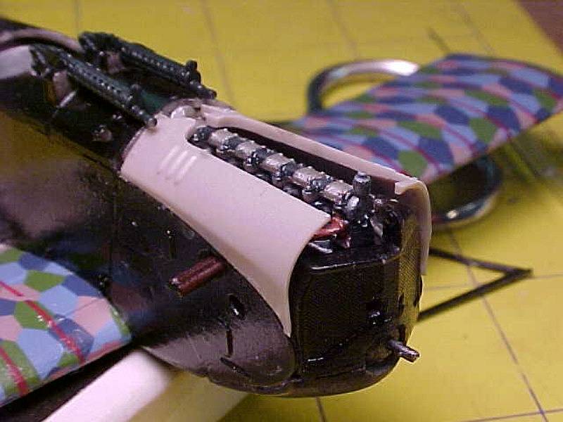
After this, I finished up the rest of the interior details and parts
and moved on to that fiddly engine and cowling. Read all of the other
Roden D-VII reviews you can find on the web, and most of our fellow modelers
have commented on the fit of the cowling in this kit. They insist that
it is far too big. I personally believe that is because they tried to
install too many parts. I looked at my earlier 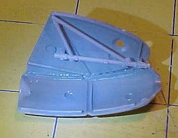 releases
of this kit and if you just follow the instructions for guidance as most
of us do, the instructions imply that step 9 and 10 are sequential, when
in actuality - they are options. Step 9 guides you through building an
uncowled engine. This results in having the cowling mounting frames, two
parts #12C, installed last. These are what you would see if the cowling
panels were off of the airframe. Step 10 guides you through building the
front end with the cowling panels on. In this step what would be parts
#12C are molded into the side panels parts #1H and #2H. I think other
reviewers may have built through step 9 then added the cowling as shown
in step 10, not noticing that you have to leave some parts off to make
things work that way. In my case, I followed just step 10; the cowling
turned out almost the right width, just a touch too wide, but not as drastic
as others have reported. However, that doesnt mean that this was a completely
smooth assembly either. I used the following sequence, I glued the left
side panel on to the lower pan, making sure they were perpendicular to
each other. This was followed by the left engine mount part #26B.
releases
of this kit and if you just follow the instructions for guidance as most
of us do, the instructions imply that step 9 and 10 are sequential, when
in actuality - they are options. Step 9 guides you through building an
uncowled engine. This results in having the cowling mounting frames, two
parts #12C, installed last. These are what you would see if the cowling
panels were off of the airframe. Step 10 guides you through building the
front end with the cowling panels on. In this step what would be parts
#12C are molded into the side panels parts #1H and #2H. I think other
reviewers may have built through step 9 then added the cowling as shown
in step 10, not noticing that you have to leave some parts off to make
things work that way. In my case, I followed just step 10; the cowling
turned out almost the right width, just a touch too wide, but not as drastic
as others have reported. However, that doesnt mean that this was a completely
smooth assembly either. I used the following sequence, I glued the left
side panel on to the lower pan, making sure they were perpendicular to
each other. This was followed by the left engine mount part #26B.
 The
instructions lack clear guidance as to exactly where this part should
go. I ended up moving it as far forward as the lower pan would allow.
This allowed the upper mounting point of part #26B to line up with the
corresponding point on the side cowling. I then added the right cowling
and engine mount also attaching to the bottom pan. Then I verified that
the engine was going to fit. And it did. Now in the most radical departure,
I glued these parts to the front of the fuselage at the firewall.
The
instructions lack clear guidance as to exactly where this part should
go. I ended up moving it as far forward as the lower pan would allow.
This allowed the upper mounting point of part #26B to line up with the
corresponding point on the side cowling. I then added the right cowling
and engine mount also attaching to the bottom pan. Then I verified that
the engine was going to fit. And it did. Now in the most radical departure,
I glued these parts to the front of the fuselage at the firewall.
 The
cowling didnt match up perfectly to the rest of the fuselage but it was
acceptable, and the wing fit with a little work. Once this dried thoroughly,
the engine was glued in place, followed by the radiator. Again, a significant
amount of trimming and scraping was needed to make the radiator fit. Lastly,
the straight exhaust was fitted through the cowling.
The
cowling didnt match up perfectly to the rest of the fuselage but it was
acceptable, and the wing fit with a little work. Once this dried thoroughly,
the engine was glued in place, followed by the radiator. Again, a significant
amount of trimming and scraping was needed to make the radiator fit. Lastly,
the straight exhaust was fitted through the cowling.
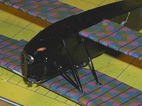
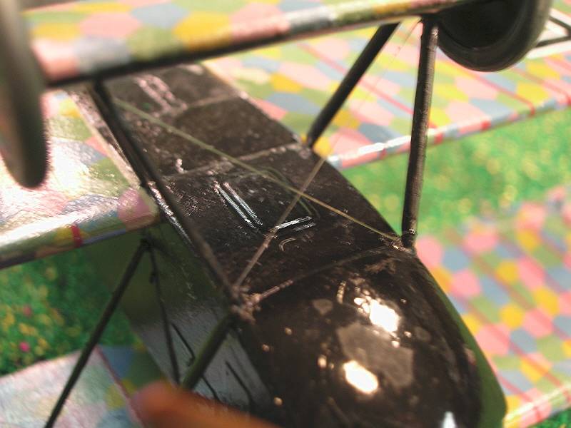
In a rush to meet IMs publishing deadline last month, I decided to leave the top cowling parts off because it appeared theyd fit just fine and Id get them later. After getting a months reprieve, I went back to a completely cowled model. As the following two pictures show, the upper cowling in this kit has a considerable warp.
 |
 |
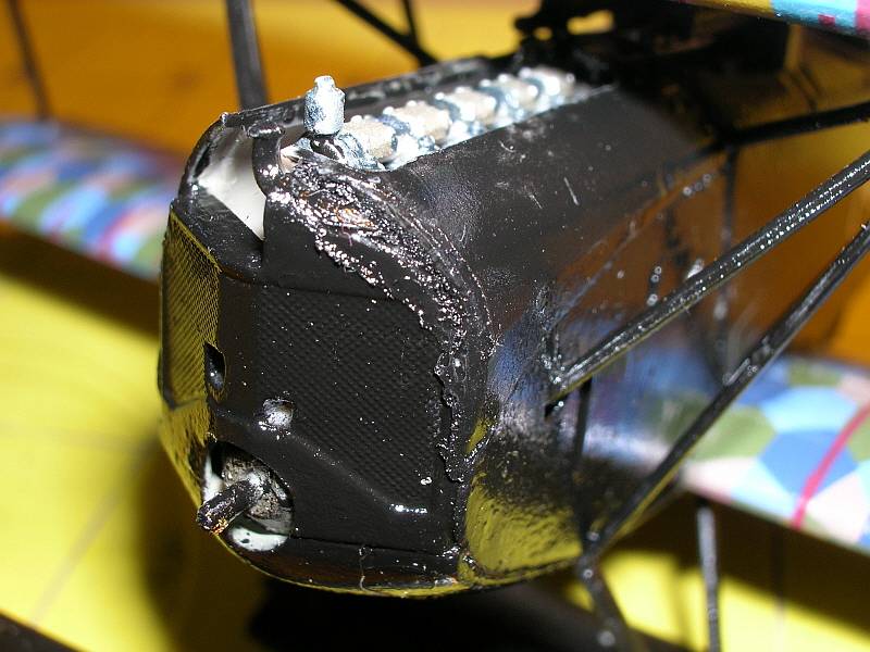 I
tried to resolve the warp in three steps. First I firmly glued the aft
end of both top cowlings to the fuselage, then carefully matched and glued
the curved sections down to the middle cowling,
Lastly I was a little enthusiastic on applying TENAX to make the warped
front end stay attached to the cowl.
The melted plastic ooze made a little mess on the side of the radiator!
I
tried to resolve the warp in three steps. First I firmly glued the aft
end of both top cowlings to the fuselage, then carefully matched and glued
the curved sections down to the middle cowling,
Lastly I was a little enthusiastic on applying TENAX to make the warped
front end stay attached to the cowl.
The melted plastic ooze made a little mess on the side of the radiator!
One last note, if you want to build
this airplane with the cowling off, you still need to do some surgery.
If youll look at one of the side cowlings note that it is two sections;
a "D" shaped panel in front and a triangle - shaped panel in
back. On this early batch of 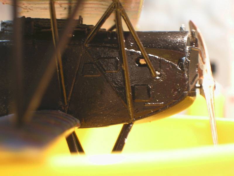 Albatros
produced airplanes, the aft triangular panel was fabric covered, and remained
on the airplane at all times. Only the "D" - shaped panel was
removable. So to properly do an open cowl on this bird, youll have to
follow step 9 to install the open engine, then cut the triangular sections
off of the side cowls, sand the details off the inside of the triangles
then attach them to the fuselage at the firewall.
Albatros
produced airplanes, the aft triangular panel was fabric covered, and remained
on the airplane at all times. Only the "D" - shaped panel was
removable. So to properly do an open cowl on this bird, youll have to
follow step 9 to install the open engine, then cut the triangular sections
off of the side cowls, sand the details off the inside of the triangles
then attach them to the fuselage at the firewall.
Okay engines on. Lets close out the fuselage. Start by dropping the font fuselage top, complete with fuel tank and ammo magazines, on to the fuselage. Oops, the magazines hit the fuel pump. So way back at the top of this article, when were detailing out the interior, be sure to mount the fuel pump UNDER the locating pins on the RH fuselage side. This was followed by pre fitting the lower wing to the fuselage. Several other reviewers have heavily emphasized that the gap between the lower wings is too small or the fuselage is just too wide. So a slightly more than - normal amount of time and work is needed to get the wing to just drop into position, to ensure you dont build in anhedral when you go to finally glue things together. My last pre-painting, pre-assembly action was to drill out the flight control cable pass through with a #77 drill bit. Why the odd size? Because that was the size of the holes in the plastic.
 Thanks
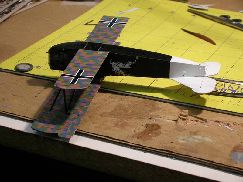
to the nice simple paint scheme, painting went quickly and painlessly.
Tail feathers and the back of the fuselage were shot with Model Master
gloss white enamel. The fuselage and sub wing were masked off and then
shot with Model Master gloss black.
Thanks
to the nice simple paint scheme, painting went quickly and painlessly.
Tail feathers and the back of the fuselage were shot with Model Master
gloss white enamel. The fuselage and sub wing were masked off and then
shot with Model Master gloss black.
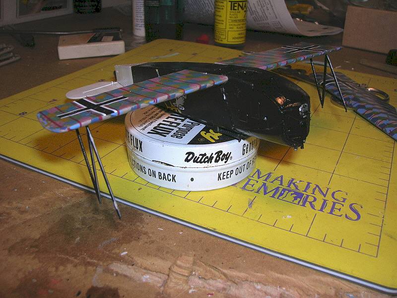
We finally moved on to getting the parts to look like an airplane. The lower wing, stabilizer and elevators were attached. Now for the most frustrating part of all biplanes, getting all of the struts to line up. Fortunately, Im going to plagiarize Tom Cleavers method from his online review of a build of an earlier Fokker D-VII. In this case, the "N" struts of the D-VII rise perpendicular to the lower wing. I simply glued the "N" struts to the lower wing and allowed them to dry overnight with the struts hanging down.
Once these "N" strut joints were thoroughly dry, the top wing was fitted and glued on. Propping the tail up slightly allowed the full weight of the fuselage and lower wing assemblies to get a good joint at upper attach points on the bottom of the top wing.
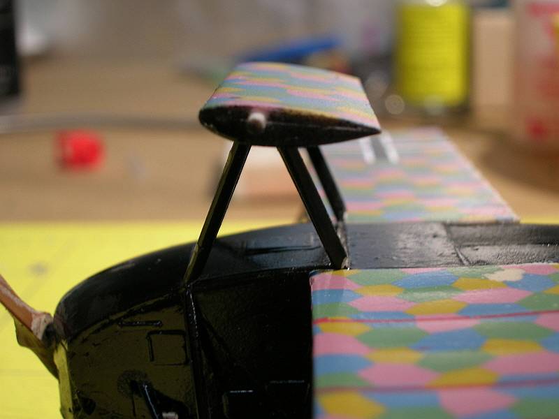
 Take
great care at this point because the wing is very fragile. Roden has done
an EXCELLENT job of molding the ball-and-socket struts used by Fokker,
and this makes some of the rest of the wing assembly a little easier.
So the next step in getting the top wing firmly attached to rest of the
plane is to fit the "V" - shaped struts, or cabane struts to
the front spar. The front leg of this strut passes through the cowl and
attaches to the engine mount. But if you are building a closed cowl, like
I did, then this front leg is slightly too long. I wound up cutting about
1/16th of an inch, in 1/64th increments, off the
portion that sticks into the cowling to get a good fit. This allowed the
left - hand cabane to easily fit between the upper forward fuselage, the
front spar of the top wing, and the hole in
the cowling. On to the right side, GRRR, the engine exhaust stack interferes
with the cabane strut. My solution was to cut the exhaust, make it shorter,
and allow the strut to fit. With the two front cabanes now providing a
bit more rigidity, I added the aft cabanes. These ended up too long, but
they are just the right length if you cut off the little round end fittings
and just use the strut itself. The final component in the wing rigging
is the third brace that makes the front cabanes into Fokkers signature
triangular mount. On my model these units were just the right length and
fit perfectly between the cabane and fuselage.
Take
great care at this point because the wing is very fragile. Roden has done
an EXCELLENT job of molding the ball-and-socket struts used by Fokker,
and this makes some of the rest of the wing assembly a little easier.
So the next step in getting the top wing firmly attached to rest of the
plane is to fit the "V" - shaped struts, or cabane struts to
the front spar. The front leg of this strut passes through the cowl and
attaches to the engine mount. But if you are building a closed cowl, like
I did, then this front leg is slightly too long. I wound up cutting about
1/16th of an inch, in 1/64th increments, off the
portion that sticks into the cowling to get a good fit. This allowed the
left - hand cabane to easily fit between the upper forward fuselage, the
front spar of the top wing, and the hole in
the cowling. On to the right side, GRRR, the engine exhaust stack interferes
with the cabane strut. My solution was to cut the exhaust, make it shorter,
and allow the strut to fit. With the two front cabanes now providing a
bit more rigidity, I added the aft cabanes. These ended up too long, but
they are just the right length if you cut off the little round end fittings
and just use the strut itself. The final component in the wing rigging
is the third brace that makes the front cabanes into Fokkers signature
triangular mount. On my model these units were just the right length and
fit perfectly between the cabane and fuselage.
 Last
fiddly bit to mess with was the landing gear. I made the (false) assumption
that the struts would fit into the sub-wing at the proper fore-and aft-angles,
and that all Id have to worry about was fitting the struts into the matching
sockets on the bottom of the fuselage. The good news is that it is easy
to get the struts attached to the fuselage; the bad news is the sub-wing
ended up a little nose low. Next time Im going to use glue that will
allow me to adjust all six contact points before the glue sets.
Last
fiddly bit to mess with was the landing gear. I made the (false) assumption
that the struts would fit into the sub-wing at the proper fore-and aft-angles,
and that all Id have to worry about was fitting the struts into the matching
sockets on the bottom of the fuselage. The good news is that it is easy
to get the struts attached to the fuselage; the bad news is the sub-wing
ended up a little nose low. Next time Im going to use glue that will
allow me to adjust all six contact points before the glue sets.
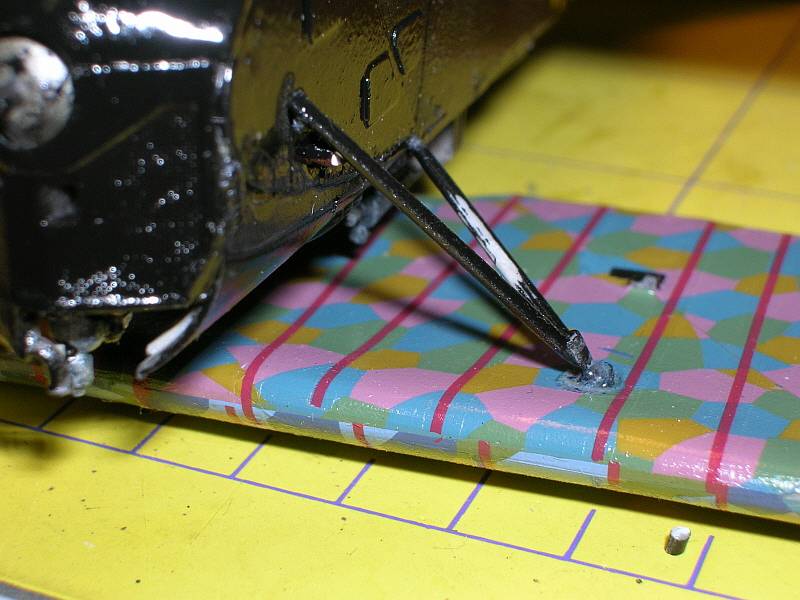
The last of the detail parts were added, paint touched up where needed, and the little rigging on the aircraft was done, and pictures shot. If youve never rigged a biplane, I strongly suggest that you add the two little cross brace wires to the landing gear struts. It greatly improves the strength of this structure.
I had a lot of fun with this kit and learned how to deal with lozenge and rib tape decals. Hint - rib tapes, caffeine and alcohol do not mix. Do them only when you are awake and sober.
Conclusion
 In
summary, things to be prepared to do before you press on with this kit
are:
In
summary, things to be prepared to do before you press on with this kit
are:
- Make sure the ailerons, elevator and rudder are trimmed to fit the matching components.
- Clear out the holes in the rudder bar and joystick to allow the aileron torque tube to pass through.
- The bottom radiator flap mount will interfere with the engine, so you need to do some trimming and fitting if you want both to show.
- Make sure theres a gap between the magnetos.
- Enlarge the engine exhaust pass - through hole in the cowling to the back of the panel and install the exhaust stack as far aft as it will go. This may let it clear the cabane strut.
- The fuselage and cowling are just a tad too wide to install the lower wings without having them develop anheadral. File or scrape the fuselage and wings until you get a free fit that doesnt bend the wings downward.
- Attach the lower wing first, followed by the "N" struts, followed by the cabane struts.
- Use cross bracing on the landing gear.
 Things
Id like to see Roden improve in this kit:
Things
Id like to see Roden improve in this kit:
- They went through the effort to include propeller decals. The cockpit in this airplane is very open, and all of the gauges are very visible, it would be nice to have decals for the instrument faces. Theyd be about the same size as the prop decals.
- Adding a comment that you have to cut the cowling to get a correct open engine would also be a nice touch.
- And the only actual error in the whole kit part #6C and #11B are cross-labeled. #11B is the short one.
I thank IM and Roden for this review kit, straight from the factory.
References
Flying Scale Models, Vol 7 No. 51, Fokker D-VII special
Albatros publications Fokker D-VII Anthologies 1,2 & 3
 |
 |
 |
 |
 |
|