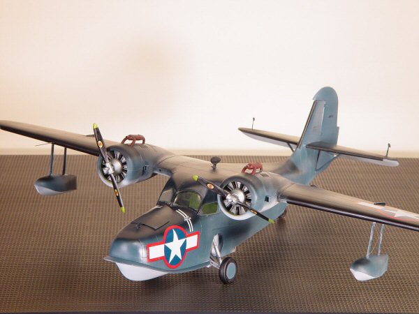
Czech Model 1/48 Grumman JRF Goose
|  |
The Kit
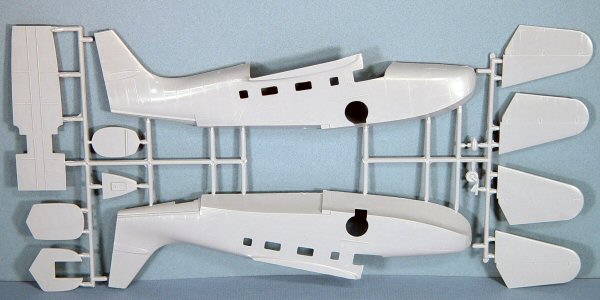
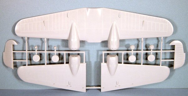
The Czech Model 1/48 JRF Goose is a nice looking kit. Molded in light
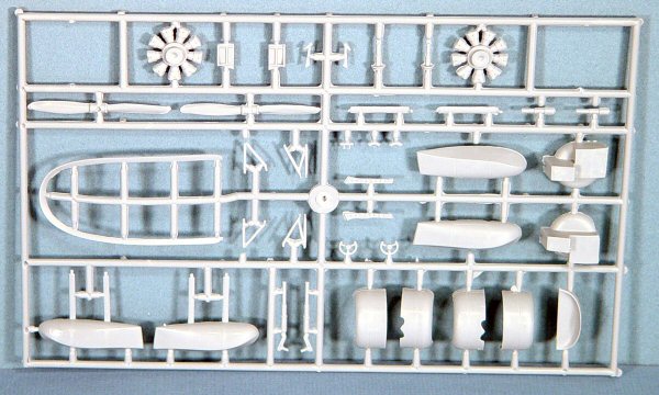
gray styrene, the kit is provided on three parts trees and features nicely
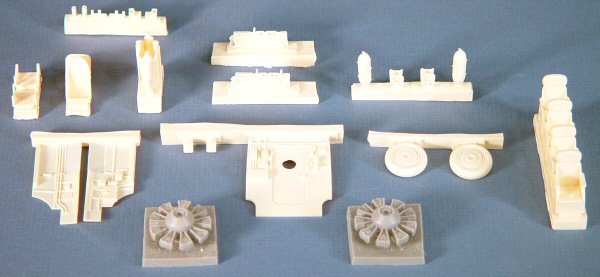
scribed details on the exterior surfaces. An additional assortment of
resin parts are also provided to round out the kit with interior seating,
engines, exhaust manifolds, carburetor intakes, cockpit rear bulkhead
and sidewalls, wheels and other miscellaneous details. One small tree
of clear styrene parts provides the cabin windows and cockpit overhead
enclosure.
Straight out of the box, this is a limited run kit and as such, will
require the usual amount of dry fitting and sanding/filing to get all
of the parts to come together. There are the usual ejector pin marks and
stubs in places that will require attention before assembly. The worst
of these were located inside the main wheel wells which are quite visible
and mar the otherwise nice detail molded into these parts.
I haven’t seen a full-scale Goose on the ramp in years and I had
lost perspective on just how large this aircraft really is until I parked
the completed model on my shelf. The assembled aircraft is roughly the
size of the de Havilland Mosquito in length and width, though quite a
bit taller to accommodate the boat hull.
 Assembly Assembly
I reviewed the kit’s instructions and decided to follow a different
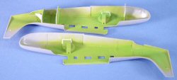
assembly path based on experience. After airbrushing all of the interior
parts with Model Master Zinc Chromate Green, I decided to dry-fit the
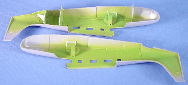
main wheel wells (parts 30 & 33) into the fuselage halves along with
the main cabin floor, which has notches molded to fit around the wheel
wells. I found that if the wheel wells are not properly aligned and cemented
into place first, the fuselage halves will not align properly once the
interior is installed.
 I
cemented one wheel well into place, centering the well over the corresponding
hole in the fuselage. This turned out to be a slight error as this partially
hid the forward holes for the lower landing gear arms inside the fuselage.
More on this later. Even with a good solid fit in the fuselage, there
was still daylight visible between the bottom of the wheel well and the
bottom of the fuselage hole. I blocked this off by enclosing this gap
with strips of Evergreen plastic strips. I
cemented one wheel well into place, centering the well over the corresponding
hole in the fuselage. This turned out to be a slight error as this partially
hid the forward holes for the lower landing gear arms inside the fuselage.
More on this later. Even with a good solid fit in the fuselage, there
was still daylight visible between the bottom of the wheel well and the
bottom of the fuselage hole. I blocked this off by enclosing this gap
with strips of Evergreen plastic strips.
With the first wheel well in place, I reinstalled the cabin floor, closed
up the fuselage halves with the other wheel well loosely in place. After
aligning and taping the fuselage halves together, I could cement the other
wheel well into place as this will now ensure that we’ll have good
alignment later. I completed this step by enclosing the base of the second
wheel well with Evergreen strips.
I cemented aft bulkhead (part 10) into the right fuselage half. This
part serves as the mount for the tailwheel well which, contrary to the
instructions, will get installed later. After the cement dried, I dry-fit
the fuselage halves together and found that the bulkhead is a bit too
wide.
I applied gap-filling cyano to reinforce the bulkhead/fuselage joint,
and then attached a cutting/grinding disk to the end of my Dremel Flexi-Shaft
rotary tool. With the fuselage halves together, I could see the parts
of the bulkhead that needed to be trimmed, which happened swiftly thanks
to my trusty Dremel. Trimming a fraction of an inch at a time, I’d
trim and dry-fit the fuselage together again until the fuselage halves
joined solidly.
Next up was the top of the tailwheel well which attaches to the rear
bulkhead we just finished. I cemented this into place, then repeated the
fit-grind-fit process until everything came together. Being a cynic at
heart, I knew that this part would eventually come loose and take the
tailwheel with it, giving the Goose an even more awkward stance. As a
precaution, I installed a sheet styrene wedge to reinforce that joint.
 The
rear cabin bulkhead was next. There is a door molded into this bulkhead,
but right over where the door handle would be was an ejector pin stub.
Since I doubted that any of this detail would be visible from the outside,
I just turned the bulkhead around and cemented it into place. After reinforcing
the bulkhead with gap-filling cyano, I repeated the fit-grind-fit process. The
rear cabin bulkhead was next. There is a door molded into this bulkhead,
but right over where the door handle would be was an ejector pin stub.
Since I doubted that any of this detail would be visible from the outside,
I just turned the bulkhead around and cemented it into place. After reinforcing
the bulkhead with gap-filling cyano, I repeated the fit-grind-fit process.
The forward cockpit bulkhead was the third and final step in this process,
repeating the steps above to get a good fit. To put this into temporal
perspective, the entire bulkhead installation and trimming process took
all of about 15-20 minutes to complete, including a few pauses to sip
my coffee.
The last bit of trimming would be the cockpit floor. I installed the
floor into the fuselage with the bulkheads in place and had to remove
a fraction of an inch from both ends to get a good fit. I could see that
the width of the floor extended beyond the trimmed forward and rear bulkheads,
so I narrowed the width of the entire floor a fraction of an inch from
both sides so as not to adversely affect the fit of the floor over the
wheel wells. With the trimmed floor back in the fuselage, the fuselage
halves now fit nicely together.
With all of the grinding done, it was time to install the side windows
into the fuselage halves. I had to file a little flash out of a few window
openings, but otherwise the windows when in place with no problems. As
I suspected, the windows are not perfectly clear as anything molded thinner
than these would be difficult to manipulate. The combination of thickness
and small size don’t allow for much visibility of the main cabin
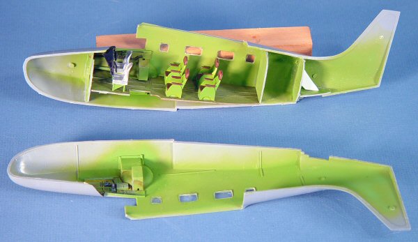
interior. While I did spend some time painting and detailing the passenger
seats, don’t worry about this as you can barely see these seats
from outside the completed model.
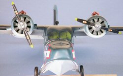
There is some nice detail in the cockpit, but about all you’ll
see from outside the completed model will be the rear cockpit bulkhead
(which is a resin part we haven’t installed yet) and the pilot/copilot
seats. I painted, weathered and detailed the instrument panel, resin cockpit
sidewalls and seat frames, but these details are not visible after the
model is completed.
With the cockpit and main cabin seats installed on the floor and the
various cockpit details completed, it was time to install the floor once
and for all. After one last safety dry-fit of the fuselage halves, I cemented
the floor into place.
It was time to cement the fuselage halves together. I used liquid cement
for the job to get a strong joint and clamped the halves together. While
I waited for the fuselage to dry, I trimmed and dry-fit the rear cockpit
bulkhead and glued this part into place.
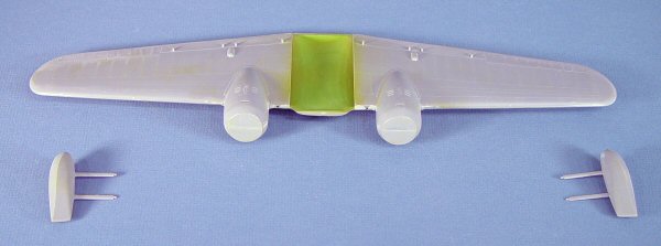
 Setting
the fuselage aside, I removed the wing components from their trees, cleaned
up the edges and cemented the subassembly together. This was also clamped
and set aside. Setting
the fuselage aside, I removed the wing components from their trees, cleaned
up the edges and cemented the subassembly together. This was also clamped
and set aside.
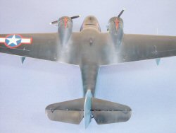
The first modification I wanted to do was to droop the elevators. I
removed the parts from the trees, then using a sharp X-Acto knife, I scribed
the stabilizer/elevator recessed line and separated these parts. After
assembling the elevators and stabilizers, I used the cutting disc to cut
out the notches on the leading edge of the elevators that represent the
hinges/attachments to the horizontal stabilizers. I cemented strips of
Evergreen into the hinge openings angled at the angle that I wanted to
droop the elevators. Once dry, I cemented the elevator/hinge assembly
back onto the horizontal stab at the new droop angle. The new hinge detail
looks great from above.
 The
mounting points for the horizontal stabs on the rear fuselage have slight
dimples molded in place to correspond with small bumps on the edge of
the stabilizer to align the assembly. I didn’t like the apparent
lack of strength of this joint, so I used a pin vise to drill holes through
the dimples. The good news is that the holes align perfectly on both sides
of the tail. I drilled corresponding holes into the ends of the horizontal
stabs and used small lengths of steel rods (trimmed clothing pins) to
act as main spars to connect the two horizontal stabs together through
the corresponding holes in the tail. The resulting joint is strong and
didn’t require much cyano to finish the assembly after painting
was completed. The
mounting points for the horizontal stabs on the rear fuselage have slight
dimples molded in place to correspond with small bumps on the edge of
the stabilizer to align the assembly. I didn’t like the apparent
lack of strength of this joint, so I used a pin vise to drill holes through
the dimples. The good news is that the holes align perfectly on both sides
of the tail. I drilled corresponding holes into the ends of the horizontal
stabs and used small lengths of steel rods (trimmed clothing pins) to
act as main spars to connect the two horizontal stabs together through
the corresponding holes in the tail. The resulting joint is strong and
didn’t require much cyano to finish the assembly after painting
was completed.
Though the rudder is molded separately from the fuselage, I cemented
the rudder halves together and used the cutting disc to open up the rudder
hinges and repeated the process above for the rudder and vertical stabilizer.
I decided not to install the rudder or horizontal stabs until after the
painting was completed to simplify the masking process.
I applied Mr Surfacer 500 to all of the fuselage and wing seams to address
any gaps and any other imperfections. Once dry, I used wet/dry sanding
sticks to dress the seams and edges.
When I dry-fit the wing onto the fuselage, I found that the wing didn’t
align quite right with the lower wing fairings molded on the fuselage
sides. This turned out to be an edge on the fuselage that wasn’t
quite square and was holding the wing off slightly. I quick trim with
the disk and the wings were snug in place. Once again I used liquid cement
to achieve a solid joint.
 Once
of the more challenging parts of the model was the transparent cockpit
enclosure. To CMK’s credit, they didn’t force you to try to
install the windscreen and cockpit side windows in the same manner as
the cabin windows. Instead, CMK molded the entire cockpit enclosure as
two halves so that we’d have some real estate to sand/fill/cement.
I dry-fit the right half of the enclosure into the fuselage and found
that the side window didn’t fit into the corresponding opening in
the fuselage. A quick trim with the cutting disk solved this problem,
but even trimmed, the fit of this part was not great around the bottom
of the wind screen nor did the side window reach all the way to the rear
of the opening. To assess the challenge, I installed the left half of
the enclosure after a similar fit and trim session and then cemented the
enclosure halves together and to the fuselage. Once
of the more challenging parts of the model was the transparent cockpit
enclosure. To CMK’s credit, they didn’t force you to try to
install the windscreen and cockpit side windows in the same manner as
the cabin windows. Instead, CMK molded the entire cockpit enclosure as
two halves so that we’d have some real estate to sand/fill/cement.
I dry-fit the right half of the enclosure into the fuselage and found
that the side window didn’t fit into the corresponding opening in
the fuselage. A quick trim with the cutting disk solved this problem,
but even trimmed, the fit of this part was not great around the bottom
of the wind screen nor did the side window reach all the way to the rear
of the opening. To assess the challenge, I installed the left half of
the enclosure after a similar fit and trim session and then cemented the
enclosure halves together and to the fuselage.
The good news was that the halves aligned together fine and the joint
with wing was great. The bad news was that there were carnivorous gaps
between the windscreen and the nose as well as the previous gaps in the
rear of the side windows. The good news is that an old trick quickly conquered
the gaps – I applied white glue to the gaps with a toothpick and
set aside the model to dry. The gaps were gone and the white glue was
painted over. I masked the windscreen and side windows with MicroMask.
It was almost time to paint the aircraft. There are six dimples molded
under each wing to locate the mounting points for the wing floats and
the anti-sway wires. I opened these up with the pin vice, but waited on
installation of the floats until after painting.
Painting and Finishing
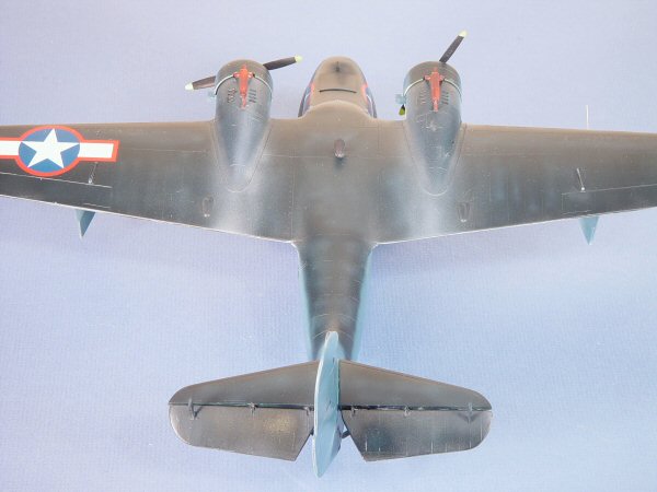
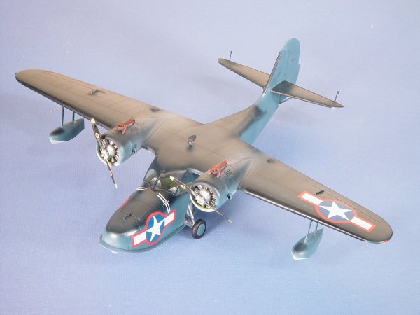
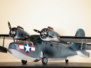
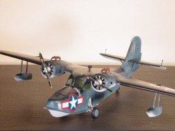
 I
decided to finish my aircraft as an early war example with the tri-colored
camouflage and the red surrounds on the national markings. There is a
color photo of a pair of JRFs in the book WW2 in Color, one aircraft equipped
with prop spinners and the other without. The photo captured the look
that I wanted on this model. I
decided to finish my aircraft as an early war example with the tri-colored
camouflage and the red surrounds on the national markings. There is a
color photo of a pair of JRFs in the book WW2 in Color, one aircraft equipped
with prop spinners and the other without. The photo captured the look
that I wanted on this model.
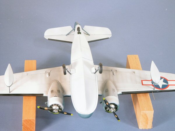
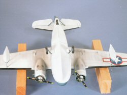
I applied two coats of Tamiya Flat White to all of the lower surfaces
of the model, buffing the surface with an old t-shirt after each coat.
I masked the lower hull and lower wing/fuselage joint to protect the white,
then applied Tamiya Medium Blue to the fuselage and floats. After buffing
this coat, I applied Tamiya Dark Blue to the upper wing/fuselage/horizontal
stab surfaces. To replicate some fading in the Dark Blue, I applied a
thinned mist of Medium Blue inside the panel lines of the upper surfaces.
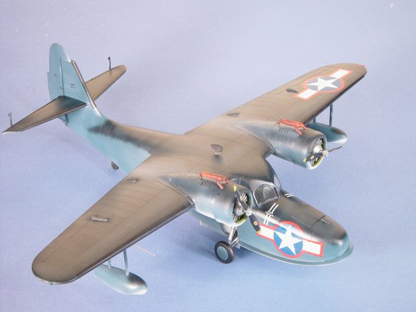
 I
masked the leading edges of the wings and vertical/horizontal stabs to
add the black anti-icing boots using Tamiya Black. While I had a little
black left in the airbrush, I sprayed a fine mist along the undersides
of the wing from the engine nacelle to the trailing edge of the wing to
replicate smoke and oil over time. A corresponding trail was left on the
upper surface of the wing using a mist of Tamiya Medium Gray. Once the
model was dry, I buffed all of the surfaces once more with the old t-shirt
to attain a smooth finish. To this I sprayed a clear coat of thinned Future
acrylic wax to the model. I
masked the leading edges of the wings and vertical/horizontal stabs to
add the black anti-icing boots using Tamiya Black. While I had a little
black left in the airbrush, I sprayed a fine mist along the undersides
of the wing from the engine nacelle to the trailing edge of the wing to
replicate smoke and oil over time. A corresponding trail was left on the
upper surface of the wing using a mist of Tamiya Medium Gray. Once the
model was dry, I buffed all of the surfaces once more with the old t-shirt
to attain a smooth finish. To this I sprayed a clear coat of thinned Future
acrylic wax to the model.
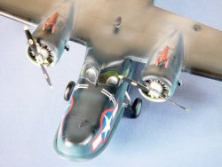
 I
sprayed the resin engines with a coat of Alclad II Aluminum, then applied
a wash of Lamp Black oil thinned in Mineral Spirits to the cylinders to
bring out the details. The prop hubs were also painted with Alclad II
Aluminum, the blades with Tamiya Black, and the tips with Tamiya Yellow. I
sprayed the resin engines with a coat of Alclad II Aluminum, then applied
a wash of Lamp Black oil thinned in Mineral Spirits to the cylinders to
bring out the details. The prop hubs were also painted with Alclad II
Aluminum, the blades with Tamiya Black, and the tips with Tamiya Yellow.
The kit decals provide markings for four aircraft, one with a tri-colored
camouflage with the early war (red surround) markings, one also tri-colored
without the red surrounds, one in the late-war overall Dark Blue, and
a British example. I opted for the first example. The kit decals are thin
and nicely in register, yet the white is opaque. Nicely done CMK! A few
words of caution – these decals don’t ‘float’
very well. Wherever you put them, they are going to want to stay there
and are difficult to maneuver. They also react very quickly to Solvaset,
so after watching my test decal scrunch up, I opted for MicroSol instead.
The national markings needed two applications of MicroSol to settle into
the surface of the model, but the final result was very nice.
Since the color photo of the JRFs showed the aircraft with a semi-gloss
(leaning toward glossy) finish, I applied another coat of Future over
the decals, then buffed the dry surface to the sheen I desired.
Final Steps
 It
was time to finish assembly. The tail feathers and engines were installed.
The rigged the floats with nylon thread to represent the cross-strut wire
braces using holes in the struts that I drilled with the pin vise. I was
going to use the nylon thread for the anti-sway braces as well, but I
wound up having a bad thread day and I’ll add the braces using brass
wire at a later date. It
was time to finish assembly. The tail feathers and engines were installed.
The rigged the floats with nylon thread to represent the cross-strut wire
braces using holes in the struts that I drilled with the pin vise. I was
going to use the nylon thread for the anti-sway braces as well, but I
wound up having a bad thread day and I’ll add the braces using brass
wire at a later date.
The next challenge was the main landing gear. As I mentioned earlier,
I centered the wheel wells over the fuselage openings, but this ends up
partially obstructing the mounting holes for the landing gear support
arms. On closer inspection, the fuselage is very thick around the wheel
well openings. I used an X-Acto knife and the cutting disk to thin the
walls from the outside, being careful not to mar the paint! With a little
work, I was able to install the landing gear per the kit instructions.
 In
the final steps, first was to add all of the delicate parts, the elevator
mass balances, exhaust manifolds, DF loop, etc., to the model. The astute
modeler will notice that the kit does not include the prominent pitot
tube for the starboard wing, this was replicated with a trimmed clothing
pin. There are also no navigation lights on the wings, these being made
from clear scrap painted with Tamiya Clear Red/Green. In
the final steps, first was to add all of the delicate parts, the elevator
mass balances, exhaust manifolds, DF loop, etc., to the model. The astute
modeler will notice that the kit does not include the prominent pitot
tube for the starboard wing, this was replicated with a trimmed clothing
pin. There are also no navigation lights on the wings, these being made
from clear scrap painted with Tamiya Clear Red/Green.
In the interest of getting this article done for this issue, I stopped
the model at this point. You’ll want to locate the landing light,
the signal lights that are molded into the lower left wingtip, and if
you’re doing a US Navy aircraft, add the HF antenna mast that sits
over the cockpit and rig the wire to the vertical stab. Check your references
to see if your bird was so-equipped.
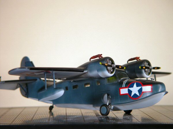
Conclusion
 This
was a fun build that didn’t take very long to finish. I don’t
think I would have enjoyed the project without the Dremel handy unless
you are looking for an upper body workout with manual files (biceps by
CMK!). The project dusted off some modeling skills as well as created
some new approaches to limited run models. As you can see by the final
result, there were no serious problems. This
was a fun build that didn’t take very long to finish. I don’t
think I would have enjoyed the project without the Dremel handy unless
you are looking for an upper body workout with manual files (biceps by
CMK!). The project dusted off some modeling skills as well as created
some new approaches to limited run models. As you can see by the final
result, there were no serious problems.
I’d recommend this project to the intermediate modeler (or better)
who has the right combination of tools and experience to exercise a little
engineering on the fly (so to speak). A basic modeler can also tackle
this project as long as you’re comfortable working with resin parts
and can exercise patience as you follow the footsteps outlined above.
My sincere thanks to Squadron Mail
Order for this review sample!
|
|