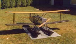
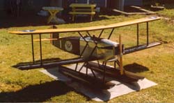
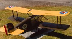
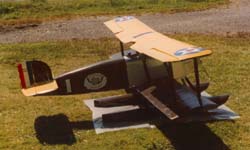
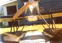
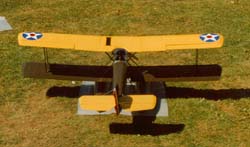
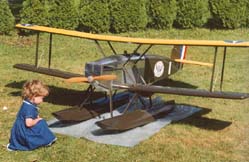
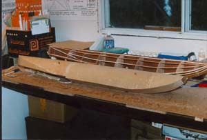
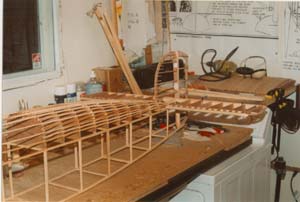
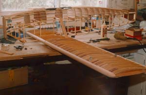
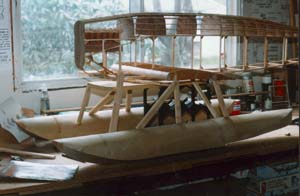
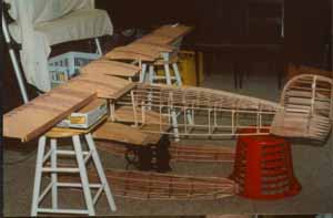
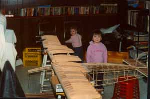
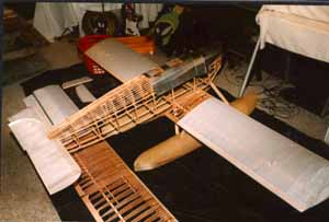
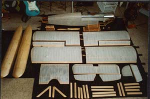
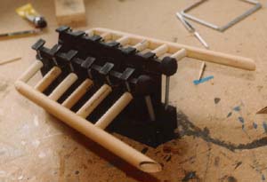
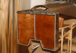
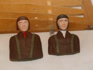
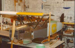
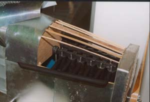
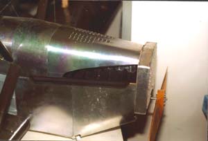
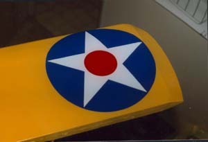
Scratchbuilt 1/6 Scale Douglas World Cruiser | 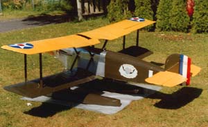 | IntroductionMany years ago I traded a friend for a copy of the December 1974 issue of WINGS magazine because it had a feature on the Albatros fighters of WWI. Another article in that same issue was on the first aircraft to fly around the world. These were the US Army's Douglas World Cruisers in 1924. I was also very surprised to find out that my hometown was the first stop for them and that one of the DWCs had a bad landing in the harbour here and broke the struts on one wing and had to be repaired locally. This article also had some nice drawings and I decided I would have to build a model of one someday. 20 years later a friend on the local heritage committee contacted me about doing a series of historically relevant aircraft painting for the local airport. A few months after this he again contacted me and said that whenever the committee presents a painting or photo to the city it just gets filed away .. so how would I like to do a model for the airport instead, and this could be an ongoing project at the rate of one per year if it works out. So we had a meeting with the various people involved and it was decided to build one of the DWCs. I was going to draw up my own plans using the set in the December 74 Wings as the basis, but a member of the WWI mailing list mentioned that Cleveland Models probably had a set that I could use ... a quick check of their website confirmed this and I placed my order for a set of 1/6 scale plans. These gave a span of 101". At about this same time I moved into a new house and set up a dedicated model room, and after lots of procrastination I purchased a table top scroll saw, table saw and borrowed a tabletop disc/belt sander. With two weeks off over the Christmas holiday I was ready to begin. The Model Work began by cutting 180 or so wing ribs out of 1/8" doorskin plywood. The first actual construction was the tail surfaces. These went together as per a balsa model with no real problems. Next up were the fuselage and float formers. To make the stringers I used the table saw to make a series of deep cuts in a 2x12 piece of wood. Then I turned the wood 90° and went back and cut these out. The first few were pretty rough due to my being terrified of the blade, but I later got it down to where I could turn out 1/8" stock pretty regularly. The floats were done with a solid keel which was notched to receive the solid formers. Originally I was going to do each side separate, but it was much easier and stronger to do each former in one piece. once the formers were added the floats were pretty rigid .. and as each one was 4' long it gave an idea as to how big the completed model would be. The fuselage was built in the manner that generation of balsa aircraft modelers will recognize. Construction began by drawing some straight lines on the workbench and nailing the upper and lower longerons in place. Vertical pieces were then glued between the longerons. Once the first side was dry, it was removed from the table leaving the nails in place and the second set was then aligned on the previous marks. The next day the two frames were turned 90° and affixed to the bench with the upper longeron now on the bottom. Crosspieces were added and when dry a basic box structure was complete. However this structure was very fragile and I lost count of the number of times frames were knocked out of place. To combat this each joint was strengthened with a plywood gusset. Once these were inplace the structure became quite sturdy and could be lifted at any point. The leading edges of each wing were constructed from two pieces of 1/4 round moulding, trailing edges were triangular mouldings – so far these were the most expensive part of the model (excepting the plans). Spars were cut from the same chunk of wood that the stringers came from (an old waterbed frame). I marked off where the ribs should go on each spar, and then after carefully aligning them the the spars were clamped to the bench and the ribs glued in place. When the ribs were dry, the leading and trailing edges were attached. Once again, numerous gussets were added to the joints. By now I was going pretty well and was confident in what I was doing and I grabbed that old Wings issue for some bedtime reading. ... while looking at the plans in it I noticed that there were no aileron control cables between each set of ailerons. ..in fact there were NO ailerons on the lower wing. I then ran down to the workshop and there it was in large print on the plans I had affixed to the wall .. AILERONS ON UPPER WING ONLY. . ARGHHHHHHHHHHHH. Luckily I had made about 40 ribs too many, so it was relatively painless to rip 14 of the short ones out of each wing and replace with the extras. Once this little panic was over, two sub-ribs were added between each full-size rib at the leading edge. The wing tips were glued to the outside rib, leading and trailing edges using numerous clamps to force them to hold the camber that the wing carries. Returning to the fuselage, the upper frames were marked with the locations of 10 stringers per side. The drawings didn't quite have them aligned properly, so I placed a stringer on top of frame 4 and 14 and marked off where it fell on the intervening frames. These were then cut out on the table saw to give an exact 1/8" width. With all the notches cut, the frames were glued to the fuselage and a keel added to the top. Finally the stringers were glued to the frames. The lower wing centre-section sits partially above and partially below the lower longeron. I decided to use solid spars through the fuselage, therefore it was necessary to construct the lower CS before adding the nose frames. Once the lower CS was done, the nose frames were built up with a series of vertical and diagonal pieces of 1/4 stock. With the basic frames just about done it was time to think about the covering materials. After questioning the WWI list I decided that the floats would be covered in 1/32" plywood, and the fabric would be done using one of the precoloured iron-on fabrics, but I was told it would look plastic and I should try going with SIG Koverall and paint it instead. The aluminum would be easy .. I asked a friend at the local newspaper for some old plates and he obliged – in one of life's little ironies. . one sheet was dated from my birthday. Eventually the fabric and plywood arrived and it was time to start covering. The floats went together a lot easier than I thought they would .. in fact it has me inspired to try my hand at a large scale ship in the near future. Covering the fabric turned out to be one of the more enjoyable aspects of the entire build. I was sent a video tape by another member of the WWI list and this showed in detail all the steps required. To cover the frames I first had to seal the wood with a couple coats of nitrate dope (I had forgotten how much it smells ... despite wearing a respirator I was woozy for days .. and my poor dog slept outside the workshop), and then giving it a thick coat of SIG STIX-IT. The fabric was then placed over the frame and using a special iron it was then ironed in place starting with the outside. Once the fabric is attached to the frames, the iron is passed over the intervening fabric and it immediately shrinks tight. A coat of dope gives it a drum-like tone when hit .. most satisfying. The only parts of the model not scratchbuilt by myself were the radiator, propellor, pilots and turnbuckles. The radiator came about due to a local airline wishing to be involved and they paid for a local machine shop to make the outline of the radiator for me. I added the triangular top, back, inside and the louvres. They did a nice job of it and it sure saved me the hassle of doing one up. The prop was found for me by yet another list member and a quick phone call had it on the way to me. Turnbuckles came from the same shop that I ordered the fabric and wood from. The pilots were from the shop and another listee. I spent an evening painting the pilots. . my first plastic model making in almost a year. With the model covered it was time to paint it. I had a local hardware store mix up a batch of olive drab and bought a can of yellow (the last one they had). The fabric below the cockpits was airbrushed silver, and I tried to airbrush the yellow on the upper wing, but that was getting me nowhere, so I tried a can of spray paint. This went on nicely, but the colour was not the same as that on the cover. Finally I bought a can of Tremclad spray paint and this did the job nicely. The OD was brushed on by hand using numerous of those disposable foam brushes. The engine was made from various chunks of wood laying about, while the exhausts were made using the handles from the previously mentioned brushes. Struts were from rectangular wood that was sanded to an aerofoil shape on the belt sander. The ends of each strut were drilled out to accept various brackets to attach them to the wings and/or fuselage. On a model this size, the rigging is functional and it is the landing wires that actually hold it all together. The wings slide together, the struts fit over the brackets and then the turnbuckles are tightened on the landing and flying wires. Once these are taut, it is possible to lift the entire model by a wingtip ... I have done so once or twice, but promise to never do so again. The floats have their struts epoxied in place and these are screwed to the fuselage and lower wing CS. I'm tempted to epoxy the floats to the fuselage, except that would make it exactly the same width as the doorway to my basement, so it will stay as separate components - at least until it is out of my house and on display. The final details were the markings. Thanks must once again go the the WWI list, which led to a friend of a friend with a sign business making me up a set of vinyl markings for the DWC logo, numeral and wing stars. The model was basically done in early June, and it sat in the bandroom for almost a month minus the floats before I disassembled it due to a party. . I put it back together in the workshop, where it again sat until I added the transfers. Finally, last week, the whim hit to see it all together outside, so I set it up in my backyard and called everyone I could think of to come and view it. . it even made the front page of the local newspaper. Conclusion It was a project that I had mixed feeling about building, as I wasn't too sure how I was going to do various aspects of it. But once started I really enjoyed it. The DWC is once again in pieces pending its public unveiling in mid-September. After that, I am looking forward to doing more large projects .. who knows, I may just do that large PBY the committee originally wanted. Thanks to Paul Wright, Tom Solinski, Steve Perry, Dave Fletcher, Ken Acosta, Knut Erik Hagen and any others of the WWI List whom I may have forgotten.
| 


|

