AER Models 1/72 Artillery Tractor STZ-5 with BM-13 Katiusha Rocket Jet Volley System By Bill Kreuger | 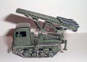 | Background: During World War 2, the Russian use of the ZIS-6 truck mounted with the Katiusha rocket volley system displayed limited maneuverability during their use on marshy and wooded areas of the battlefield. This brought about the Russian idea of mounting the rocket volley system on the back of a tracked vehicle. The STZ-5 was a tracked Russian heavy artillery tractor that would suit the purpose exactly. The design department of the Moscow "Communar" plant, the main creator of the rocket volley systems, developed a variant of the BM-13 Katuisha launcher on the chassis of the STZ-5 tractor. The system, which was called "BM-NATI", proved to be a good one. It had good cross country ability, which was not available in the wheeled chassis type systems. In the Russian Army, the rocket volley system on the chassis of the STZ-5 tractor was nicknamed "Nadiusha". The Kit 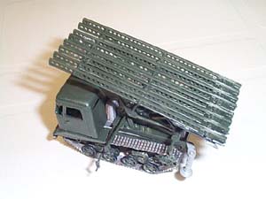 I am not familiar with AER, having never done any of their kits in the past. However, I am always up for a challenge, and this little kit presented a pretty good one for me. It is a 1/72-scale armor kit that is produced in a dark gray resin that has been squash molded. I am familiar with resin kits, but I had never done any squash molded kits before. Be advised that for those unfamiliar with this type of production, everything needs to be cut out and cleaned up "flash-wise" before assembly. I am not familiar with AER, having never done any of their kits in the past. However, I am always up for a challenge, and this little kit presented a pretty good one for me. It is a 1/72-scale armor kit that is produced in a dark gray resin that has been squash molded. I am familiar with resin kits, but I had never done any squash molded kits before. Be advised that for those unfamiliar with this type of production, everything needs to be cut out and cleaned up "flash-wise" before assembly. The kit consists of approximately 117 small resin parts that seem to be nicely molded and the detail in the running gear is very evident. There are also four pieces of brass rod, to be used as axles and as transmission linkage. The model even provides scale engine and transmission housings. I also was impressed with the detail in the rocket rails; it is very good for a kit of this size. The parts come in 16 sheets of resin that are inside of one large and three small zip-lock plastic bags. The bags are inside an end-opening box with a photo of the completed model on the box top. Keep this photo around, as it will come in handy when you are assembling the kit; at least it did for me. 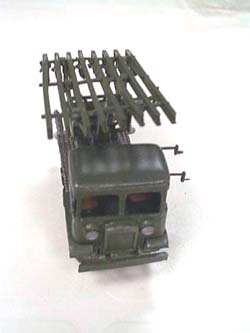 The instruction sheet provides a history/description of the vehicle, as well as a diagram of all the resin sheets, showing where various parts are located when you begin assembly. The instructions consist of 11 exploded diagrams showing how parts are to be placed and glued together. The instruction sheet provides a history/description of the vehicle, as well as a diagram of all the resin sheets, showing where various parts are located when you begin assembly. The instructions consist of 11 exploded diagrams showing how parts are to be placed and glued together. Construction: I began my assembly of the kit by washing and drying all the sheets in soapy water to get rid of any mold release agents. The first step is the assembly of the tractor's lower chassis sidewalls to the transmission housing. You need to carefully cut these pieces out of the resin sheets. For all of this, I used my No. 10 Xacto blade. After cutting, you need to clean the excess resin flash off the pieces and from any openings in the sidewalls. I used both sandpaper and a small file for this work. This step includes part numbers 1 and 2 (the sidewalls), 3 (transmission housing) and a piece of brass rod, the transmission linkage. There are no holes or locating pins in which you insert the transmission housing, just a round section of resin on the side walls that indicates the correct location. Unfortunately, the instructions are not much help. This step is also very "fiddly" since the front section has nothing it is attached to, so it would be wise to devise a jig of some sort to hold this section as it is being assembled. Additionally, the instructions provide no guidance for the length of rod you need to cut for the linkage. You are on your own with your best measurement. Please note that the engine is not attached until step 5. I went on ahead and assembled the engine housing to the cab floor board (Step 2) and then skipped to Step 5, which has you attaching the engine and cab floor board to the lower side walls. 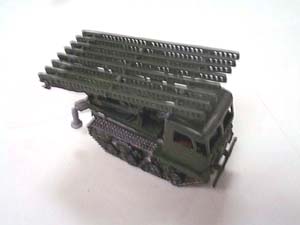 Step 2, as indicated above is the assembly of the engine housing and its attachment to the underneath side of the cab floor board. This step is fairly easy but in my kit I had to cut out additional resin in order to allow the engine to fit into its seat squarely. There is a notch provided in the underneath side of the flooring, which is where the instructions show you to place the engine. Step 2, as indicated above is the assembly of the engine housing and its attachment to the underneath side of the cab floor board. This step is fairly easy but in my kit I had to cut out additional resin in order to allow the engine to fit into its seat squarely. There is a notch provided in the underneath side of the flooring, which is where the instructions show you to place the engine. After this, I skipped to Step 5 and finished the assembly of the chassis. Here you attach Step 2 to the chassis sidewalls. I also, at this point, measured and attached the brass rod to the engine and then linked it to the transmission. You also assemble the front and rear bumpers and attach them to the chassis. The back bumper has something of a guide that is the notched end of the sidewalls, into which it fits well. The front bumper is placed between the chassis sidewalls and attached, but there is no real guide to show you how deep to place it. The box photo provides some help for you. 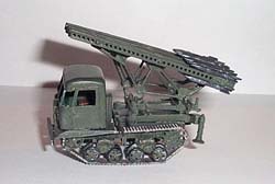 After this, I went back to Step 3, which is the assembly of the bogie wheels. The bogie wheels are extremely small, but they need to be carefully cut out of their resin sheet and cleaned up. The clean up includes filing away excess resin between the spokes, a very time consuming job. The bogies are then glued to the springs; there are two pair of bogies to each set of springs. The springs also need to be cleaned up, but not as much as the bogies. You make four sets of bogies in this step. After this, I went back to Step 3, which is the assembly of the bogie wheels. The bogie wheels are extremely small, but they need to be carefully cut out of their resin sheet and cleaned up. The clean up includes filing away excess resin between the spokes, a very time consuming job. The bogies are then glued to the springs; there are two pair of bogies to each set of springs. The springs also need to be cleaned up, but not as much as the bogies. You make four sets of bogies in this step. Next you attach the sets of bogies to the axles. The kit provides the brass rod that is to be used for the axles; however, I opted to use Evergreen 3/64" plastic rod instead. The plastic rod is the same diameter as the brass rod and it was easier to use and cut, in case I made a mistake. Again, the instructions do not specify how long the rod is to be - you need to make your own measurements. After making the correct measurements, I cut each section of rod to length and glued the bogie sets to them. You wind up with two sets of wheels. 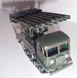 Since I had already completed Step 5, I moved on to Step 6, which is the assembly of the wheels to the chassis. The chassis has prongs, which are the locating pins for the bogie assemblies. You simply glue the axles to these. You may need to do some filing here to make sure the axles fit into their assigned grooves. This step also has you assembling the drive and idler wheels to the chassis on each side. These wheels need to be cut out, and cleaned up just like the bogies. They are a little larger and easier to handle. Since I had already completed Step 5, I moved on to Step 6, which is the assembly of the wheels to the chassis. The chassis has prongs, which are the locating pins for the bogie assemblies. You simply glue the axles to these. You may need to do some filing here to make sure the axles fit into their assigned grooves. This step also has you assembling the drive and idler wheels to the chassis on each side. These wheels need to be cut out, and cleaned up just like the bogies. They are a little larger and easier to handle. The next step is the assembly of the tractor's cab and interior. The kit does not provide much of a detailed interior, except for two seats and something of a control panel/dashboard. There are no control columns, pedals, etc. If you want to scratchbuild this you can do that. Additionally, the kit provides no clear plastic for the windows, even though the box photo shows "window glass." You can also add this if you choose.  Just like everything else, the component parts of the cab need to be cut out and cleaned up. In this case, window openings also need to be cleaned out with a small file or sanding stick. I began with the interior, attaching the seats to the floor. Here there are depressions, which indicate where the seats are to be placed. The seats look to be as if they are on a pedestal and it is this "pedestal" that is supposed to fit into the depression in the floor. You will need to test fit and probably cut out the area where the seats go, in order to have them sit properly. When this was completed, I attached the front and right door to the floor. Here you also need to make sure the doors are at the right angle to meet the back section of the cab before you actually glue them in place. When this was all dry, I attached the left door, then painted the interior. Just like everything else, the component parts of the cab need to be cut out and cleaned up. In this case, window openings also need to be cleaned out with a small file or sanding stick. I began with the interior, attaching the seats to the floor. Here there are depressions, which indicate where the seats are to be placed. The seats look to be as if they are on a pedestal and it is this "pedestal" that is supposed to fit into the depression in the floor. You will need to test fit and probably cut out the area where the seats go, in order to have them sit properly. When this was completed, I attached the front and right door to the floor. Here you also need to make sure the doors are at the right angle to meet the back section of the cab before you actually glue them in place. When this was all dry, I attached the left door, then painted the interior. 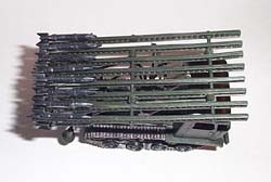 I used Olive Green (Tamiya XF-58 acrylic) for the interior walls and flooring. I painted the control panel flat black and picked out details by dry brushing with steel color. The seats were painted with Tamiya Red Brown (XF-64 acrylic). When this was dry, I completed the cab by adding the back and painting its interior. I then painted the interior of the roof and added that. I chose not to add the fenders at this time, waiting instead to install the treads first. I attached the completed cab to the chassis, making sure there was room for the fenders after the track installation. I used Olive Green (Tamiya XF-58 acrylic) for the interior walls and flooring. I painted the control panel flat black and picked out details by dry brushing with steel color. The seats were painted with Tamiya Red Brown (XF-64 acrylic). When this was dry, I completed the cab by adding the back and painting its interior. I then painted the interior of the roof and added that. I chose not to add the fenders at this time, waiting instead to install the treads first. I attached the completed cab to the chassis, making sure there was room for the fenders after the track installation. 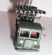 I jumped ahead to the assembly of the tractor's bed, leaving the track for later. In the process of cleaning up the bed itself, I broke off one of the prongs that sticks off the back of the bed. I had to re-glue this to the bed. After this, I ran into several other parts that seemed to break easily in the clean-up process. It appeared that some of the resin was "honey-combed" and was weakened. The slightest amount of pressure would cause that section to break. Other than the small breakage, the bed went together easily. I jumped ahead to the assembly of the tractor's bed, leaving the track for later. In the process of cleaning up the bed itself, I broke off one of the prongs that sticks off the back of the bed. I had to re-glue this to the bed. After this, I ran into several other parts that seemed to break easily in the clean-up process. It appeared that some of the resin was "honey-combed" and was weakened. The slightest amount of pressure would cause that section to break. Other than the small breakage, the bed went together easily. After the bed, I began the cleaning and assembly of the rocket rack framework. This is probably the most difficult operation of the entire kit. The parts are thin and spindly and I broke a few sections in the process of cleaning them. You need to really take your time putting this together. I began by gluing part 44 to the outside left frame (part 37). There are locating holes indicating where the pieces of the framework are to go. The instructions also point this out, but not too clearly. When this was dry, I added part 45 (the front part of the frame) to the same outside frame. When this was dry, I attached part 43 (the rear part of the frame) to the same side as the others, and finally added part 42 (middle frame). When these were all dry and strong, I carefully put the right side frame to the assembly. I was able to very carefully clamp this together to allow it to dry. 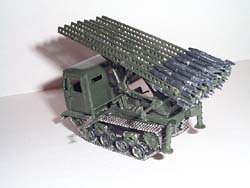 Step 11 began with the construction of the rocket rack. This was pretty straight forward as each rail has a locating pin which, in turn, matches up with a hole in the next section. You just need to make sure the two end pieces are properly located. Clean up of this section included filing out the small holes in each rail, about 25 in each one that needs to be cleaned up. When this is completed, it fits into the framework that was assembled in the last step. Make sure the arms of the framework are properly cleaned up, or else the rack will not seat well. Once this is seated, then you attach covers over the arms of the sections of rack that are seated into the framework. Then everything is glued to the tractor bed that was completed earlier. This operation is not too difficult; I did have to clean out the holes in the section of the bed where the frame is attached in order to allow the pin (part 32) to clear both sides of the frame. Step 11 began with the construction of the rocket rack. This was pretty straight forward as each rail has a locating pin which, in turn, matches up with a hole in the next section. You just need to make sure the two end pieces are properly located. Clean up of this section included filing out the small holes in each rail, about 25 in each one that needs to be cleaned up. When this is completed, it fits into the framework that was assembled in the last step. Make sure the arms of the framework are properly cleaned up, or else the rack will not seat well. Once this is seated, then you attach covers over the arms of the sections of rack that are seated into the framework. Then everything is glued to the tractor bed that was completed earlier. This operation is not too difficult; I did have to clean out the holes in the section of the bed where the frame is attached in order to allow the pin (part 32) to clear both sides of the frame. When this step was completed I went to work on the tracks. The track is molded in two long sections, two medium length sections, four small sections and a series of individual links. Although the instructions did not point this out, I used the long section for the top track, the medium length for the bottom. The small sections were connected to the bottom track to complete the lower sections of track and the individual links were used to form the sections around the idler and drive wheels and then connect the top and bottom sections of track. This was not as difficult as I had originally thought and the tracks went together rather well. When this was completed, I then attached the fenders to the front section of the tractor on both sides. At this point, I painted the tracks with Model Master Acryl Steel. When this was completely dry, I was able to dry brush with Model Master Acryl Flat Black. 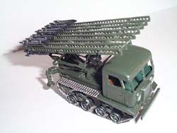 The last major assembly was the construction of the rockets. These are in two sheets of resin and are composed of the body and tail. You need to attach the tail piece to the body, where a small slot is provided. As you clean the rocket up, you also need to clean out this slot. Again, I discovered sections of the resin that seemed to be very weak. A couple of times as I was cleaning out this tail slot, a section of the tail would break off. However, I was able to keep these pieces together and assembled the rockets. I painted them Model Master Acryl Gun Metal and then dry brushed with the Steel. The rockets were then glued to the top and bottom of each rail, you have eight rails that need to be filled. When this was completed, I glued the whole piece (bed and rocket rail) to the chassis. I had to test fit this section several times and do some filing, but I was finally able to get this seated properly. The last major assembly was the construction of the rockets. These are in two sheets of resin and are composed of the body and tail. You need to attach the tail piece to the body, where a small slot is provided. As you clean the rocket up, you also need to clean out this slot. Again, I discovered sections of the resin that seemed to be very weak. A couple of times as I was cleaning out this tail slot, a section of the tail would break off. However, I was able to keep these pieces together and assembled the rockets. I painted them Model Master Acryl Gun Metal and then dry brushed with the Steel. The rockets were then glued to the top and bottom of each rail, you have eight rails that need to be filled. When this was completed, I glued the whole piece (bed and rocket rail) to the chassis. I had to test fit this section several times and do some filing, but I was finally able to get this seated properly. The final work was to paint the tractor. Some sections had already been painted, as indicated. I used a very small hand brush and an air brush to paint most of the rest of the tractor. It was finished in an overall Olive Green from Model Master Acryl. Conclusion 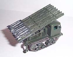 This kit is indeed a challenge, possibly one of the most difficult kits I have had the pleasure of doing in some time. It is definitely one that should be tackled by the experienced modeller. The shortcomings of this kit are many, including very general instructions, "honey-combed" resin in several areas, no clear plastic or acetate for the windows, no decals, no guide lines (except for the box photo) on colors. I would only recommend this kit to the experienced modeller, to those who enjoy a pretty good challenge, and those who want a little known piece of WW 2 Soviet history. This kit is indeed a challenge, possibly one of the most difficult kits I have had the pleasure of doing in some time. It is definitely one that should be tackled by the experienced modeller. The shortcomings of this kit are many, including very general instructions, "honey-combed" resin in several areas, no clear plastic or acetate for the windows, no decals, no guide lines (except for the box photo) on colors. I would only recommend this kit to the experienced modeller, to those who enjoy a pretty good challenge, and those who want a little known piece of WW 2 Soviet history. I want to thank Ray Mehlberger and AER for providing this kit.
| 


|
