Roden 1/72nd Albatros D.I | 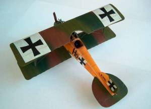 | History The Albatros D.I was the answer Germany came up with in late 1916 to try to regain the air superiority it had enjoyed before the arrival on the fighting skies of the sleek Nieuport scouts and the DH2 that, in their turn, managed to temporarily subdue the devastating effects of the infamous Fokker Eindecker. The nicely streamlined aircraft would over the years evolve from the slab sided D.I to the gracious fishlike D.V in what was to become one of the most produced aircraft series of the whole war. The Kit 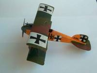 As a quick check of Roden's catalogue proves, it has been the policy of the company to extract as many versions as possible from one basic set of tooling for any given aircraft kit they set their engineering minds on. As a quick check of Roden's catalogue proves, it has been the policy of the company to extract as many versions as possible from one basic set of tooling for any given aircraft kit they set their engineering minds on.
I for one am quite happy with this as even though some compromises have to be made to allow for the easy "transfiguration" of a basic part into its various variants, that sometimes translate into a bit more of work during assembly, I think that just to be able to have at one's disposal 10 different members of the Albatros fighter family more than compensates for this. Several reviews of Roden Albatros D. fighters have appeared lately over the Internet, and our beloved IM is, of course, no exception and a very beautiful Oeffag D.II made by regular contributor Michael Kendix can be found in the September 2002 edition. Having already bagged a couple of Oeffag D.IIIs (pictures of one at the World War I Modeling Page) I decided to try my hand at where it all began and grabbed Roden box ref.001 from my stash of unbuilt kits. Construction 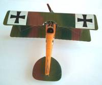 First thing I did was to assemble the multi-part wing (remember what I said about getting the most of one basic set of moulds?....). Now this is not particularly difficult and I used my usual picking on other people's brains technique (in this case modeller and friend Shane Weier whose gorgeous work can also be visited at the World War I Modeling Page): bring the 3 parts together and push the leading edge against some sort of rigid stopping surface, be careful to lift the trailing edge of the centre section with a bit of card underneath it, since that way it'll be sure to follow the curvature of the other adjoining sections. Carefully run liquid glue over the joints and capillarity will do the rest for you. A touch with your favourite brand of filler on the joints when dry will even it all out. First thing I did was to assemble the multi-part wing (remember what I said about getting the most of one basic set of moulds?....). Now this is not particularly difficult and I used my usual picking on other people's brains technique (in this case modeller and friend Shane Weier whose gorgeous work can also be visited at the World War I Modeling Page): bring the 3 parts together and push the leading edge against some sort of rigid stopping surface, be careful to lift the trailing edge of the centre section with a bit of card underneath it, since that way it'll be sure to follow the curvature of the other adjoining sections. Carefully run liquid glue over the joints and capillarity will do the rest for you. A touch with your favourite brand of filler on the joints when dry will even it all out.
I then turned my attention to the fuselage and after scraping away some of the beautifully moulded inspection "lids" as per instructions I painted the inside of the parts Humbrol 63 in preparation for my usual "woodworking". This is accomplished by "colouring" the base coat with several shades of brown water-colour pencils, the water-colour being then buffed to blend it with a dry Q-tip. 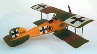 The moulded in structure was also painted in a darker shade of brown and some scratchbuilt side instrument/switch panels were installed in place following a picture of an Albatros cockpit. The moulded in structure was also painted in a darker shade of brown and some scratchbuilt side instrument/switch panels were installed in place following a picture of an Albatros cockpit.
Since on the real thing there was a fabric panel to the rear of the seat to "close" the cockpit, I replicated this with a piece of masking tape (and I didn't have to paint it since the tape is quite CDLish looking ;-). Seatbelts made of lead foil were also installed, the control column was slightly modified through the addition of a cross-member at the base that also acted as a great seam hiding device (thanks again Shane). Time to deal with the engine, and this beautiful piece of moulding is easily assembled as per instructions and painted in several shades of metallic grey.  The instructions tell us that the engine should be now inserted in place in one of the fuselage halves, but for it to fit I had to shave a bit on each side of the sump. This might not be the best solution since the front end of the fuselage is really the most troublesome area of the kit and pushing the engine in also pushes the fuselage sides a bit outward modifying its curvature. The instructions tell us that the engine should be now inserted in place in one of the fuselage halves, but for it to fit I had to shave a bit on each side of the sump. This might not be the best solution since the front end of the fuselage is really the most troublesome area of the kit and pushing the engine in also pushes the fuselage sides a bit outward modifying its curvature.
I've heard from others that it is best to close the fuselage first and then insert the engine (of course this means removing part of the side fuselage bearers) but I've yet to try it. With the fuselages halves closed I installed the front cockpit/top cowling part (23D) and this was not a perfect fit due to the aforementioned modification of the curvature that pushing the engine in imparted to the fuselage. I would also have the same problem with part 3A which is a conical ring that should fit perfectly into the front end of the fuselage but again the fit was far from perfect . Well, never one to give up easily, I faired it all in with milliput and restored the panel detail scribing with the tip of a straight pin. The ventral seam of the fuselage also needs some filling attention since probably due to some moulding flaw you end up getting a concave seam that has to be brought to shape with the filler of your choice. 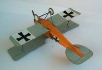 The elevator/stabilisers also benefit from gluing to each of their roots a piece of .005 card (did I say I used quite a few of Shane's ideas on this one?). If you don't do that there will be a nasty gap between the fuselage and the tailplane that will need filling. The elevator/stabilisers also benefit from gluing to each of their roots a piece of .005 card (did I say I used quite a few of Shane's ideas on this one?). If you don't do that there will be a nasty gap between the fuselage and the tailplane that will need filling.
Time to glue the lower wings on and this is another area that does require some extra care: the actual contact area between the wing and the fuselage is very small and you should do better than me and reinforce the joint by inserting pins into the wing root and drill matching holes on the fuselage sides. I didn't and have regret it ever since because while rigging the kit both wings came off.... luckily the rigging and the interplane struts held everything together and I was able to glue them on again, but I was left with a bit of anhedral on the lower wing that is not correct and wasn't there in the first place. With the lower wing on construction is now really straightforward, even the operation of laying on the top wing is easily achieved if you first glue it on by the cabanes only leaving it to dry with some sort of jig holding the wing centred and level (foam, Lego blocks, whatever...) and carefully inserting each interplane strut in its place later on. Incidentally the cabane arrangement is easily assembled if you use a piece of plasticine to hold the triangles (6/7 D) secure and then glue the cross member (22D) onto their vertexes. Painting 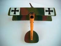 I pre-painted most of the sub assemblies this time (even both sides of the wings) since I was confident that the decals would hide all the little rigging holes that usually cause me to only paint the outer side of the top wing and the underside of the lower wing after rigging. I pre-painted most of the sub assemblies this time (even both sides of the wings) since I was confident that the decals would hide all the little rigging holes that usually cause me to only paint the outer side of the top wing and the underside of the lower wing after rigging.
Since I was looking for a natural wood/camo wings scheme I decided to settle on D.390/16, the mount of Lt. Höne in Berthincourt, 1916. Roden has this as a 2 colour camo job, but after consulting with the best source of WW1 modelling information in the world (The World War I Modeling Page) I got a message from modeller and Paschendale products producer John Cyganosky, who has thoroughly researched this subject while preparing his Paschendale D.II conversion for the Eduard kit, in which he said that he felt confident this particular aircraft might have supported a 3 colour camo job. Well, John's opinion for me is as good as law, (and I really think that the 3 camo is very cool) so all my doubts suddenly vanished and I raided the paint box to choose what colours I would use, finally setting on Humbrol 160 red brown and 158 interior green, Dyrup dark green and Extracolour X208 lichtblau for the undersides. The metal areas on the fuselage as well as the struts were left in Humbrol 31 Slate grey. Some light weathering was accomplished through drybrushing lighter shades of the colours over the painted surfaces and after rigging with invisible thread I was ready for the ... Decals 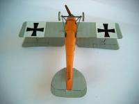 As usual with Roden, these are extremely well printed (gone seem to be the days of decal shattering that I've experienced on some earlier Rodens, like the Fokker DVI) but are not very flexible and people complain about the fact that they don't seem to react to setting solutions. As usual with Roden, these are extremely well printed (gone seem to be the days of decal shattering that I've experienced on some earlier Rodens, like the Fokker DVI) but are not very flexible and people complain about the fact that they don't seem to react to setting solutions.
Well I use Johnsons Kleer as the only setting solution on all my decal jobs and again I achieved an almost perfect decalling this way. I say almost perfect because somehow I goofed and applied the top wing crosses wrongly. Pay good attention to them because the white areas aren't perfect squares as I thought they were. When I noticed that something was wrong the Kleer had already began to set and I had to destroy the decals to be able to remove them. Luckily I had a Roden D.II in the stash, so I cannibalised the decals from it. A final coat of semi-matt varnish evened out the finish and a small windshield was cut from a piece of plastic from some blister pack that was lying around. Conclusion Do one, in fact, do two or do the whole ten (10) Roden Albatros kits. Just be careful with the engine fit and everything should be well within the skills of most modellers. As a matter of fact I'd even recommend the DI as a good introduction to biplane modelling to those that haven't yet tried it (caution: it's highly addictive, don't tell me I didn't warn you....). | 


|
