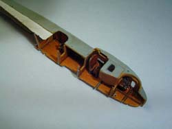
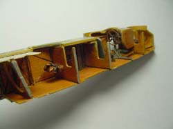
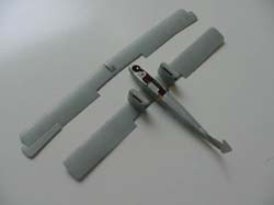
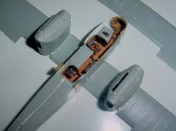
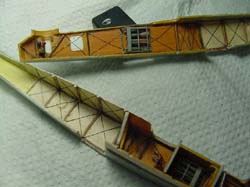
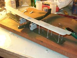
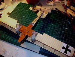
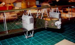
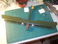
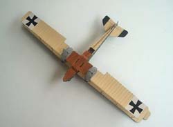
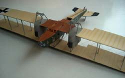
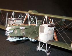
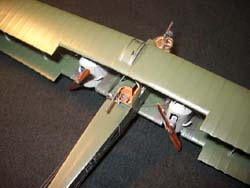
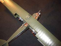
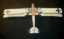
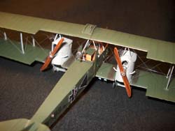
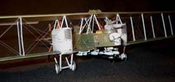
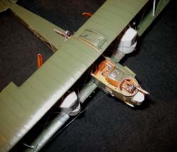
Building the 1/72 Roden Gotha G-III | 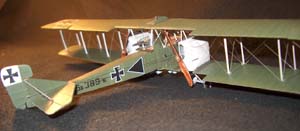 | History Mentioning "Gotha" to anyone even loosely familiar with the history of air warfare evolution (this being the case of the author of these lines) will immediately bring to mind images of the series of bombers that sorted out of the Gothaer Waggonfabrik AG during the First World War these ranged from the G-I of 1916 to the much evoluted G-VIII of 1918 (an improved, longer span version of the GVII that like its predecessor came too late to see active service) with which Germany sought to improve its strategic bombing capability. This was a concept which was also a sub-product of the war to end all wars, and which was first put to practice with the Zeppelin raids over London in 1915. This remarkable (if for not the best reasons) line of aircraft had its origin in a somewhat unconventional design by Oscar Ursinus, of a twin engined aircraft that looked like a mid wing monoplane concept with a second, lower wing, supporting the engine cells and the undecarriage, literally hanging from the top one. This design, the GI was, from the GII on, to evolute to the much more orthodox biplane configuration that would characterise the ensuing marks of the Gotha Bomber. Due to the role played in the afore mentioned strategic bombing of London, the most famous marks of Gothas were the GIV and The GV, (also already released or to be released by Roden). Still the subject of this article will be an earlier version, the GIII, used extensively in the Balkan front from October 1916 on. The Kit I won't expend a lot of words describing whatıs inside the flip top box, made out of the usual flimsy Roden card, since very good and thorough appraisals of this kit have been made before (the one that immediately comes to mind being that of Master Modeler Steve Hustad that can be easily found through a search of the archives of your favourite Internet magazine: . Suffice to say that the kit seems to be generally accurate and when finished and compared with photos of the real thing it does look like what it is meant to be: a big and aesthetically uncommon (to be kind with words) war machine, whose ugly silhouette pasted against the sky foretold the horror and anxiety of indiscriminate destruction. As far as the general quality of the kit goes, one word of caution should be emphasised though: be really careful when separating the more delicate parts, such as struts, from the sprues. I have never seen anything so brittle and at times it seemed that the parts would snap in two just by looking at them. Be prepared to substitute some struts, so I would recommend having some stock strut material at hand. This said let's go on with . . . The fuselage The large opening at the front end of the fuselage that accommodates the crew stations and the passageway will be clearly visible once the model is finished, so it's a good idea to spend some time detailing this area. As such I made a new floor from sheet plastic and added the structural members from pieces of thin evergreen strip. Conversely and since the large opening on the bottom of the fuselage, meant to allow the rear gunner to fire downwards, also makes it possible to see much of the fuselage innards, I also covered the inside of the fuselage, top and bottom, aft of the gunner's position with sheet plastic, and added plastic strip structural members. Next step was to install the cross stiffening wires and this was done with very thin copper wire glued in place with a tin drop of CA at each end. I used the Extratech PE detail set and thi, although not nearly as comprehensive as PART's, has most of the features that I think can really benefit from the use of this medium and so the PE internal bomb racks were used instead of the ones supplied in the kit which are rather thick. The crew stations were was also detailed with bits and pieces with reference to various photos published in several sources. The pilotıs seat supplied in the kit is a bit crude so I tried to improve it and voided the area between the armrest and the cushion and also rounded off the edges of the seatback. The Instrument panel came from the PE set but the one in the kit could also be used. The interior of the fuselage halves was painted in wood and CDL, the details being highlighted with watercolour and graphite pencils. The bulkheads were then added to one side of the fuselage and here do not forget stages 9 and 10 of the instruction sheet or else parts 34G and 17G won't fit. Since I had added a floor, all my bulkheads had to have a slice shaved off from their bases and when installing part 36G I committed a slight mistake since I though that the upper 'flap' of the bulkhead was meant to go under the fuselage top. This was wrong but could not be corrected when I finally noticed it, so my pilot ended up getting some more room (I think he was pleased with that.) The fuselage halves were then glued together and put aside while I concentrated on the . . . Flying Surfaces The long top wing is built of three separate parts and I thought it would be a good idea to strengthen the joints, given the size (and weight) of the wing. To this, I drilled holes in the sides of the central section and on the matching surfaces of each half wing and inserted pieces of copper wire. The wire being flexible ensures a slight degree of freedom, should the holes not be 100% aligned. I then taped the central section to a piece of board and glued unto it each of the outer sections of the wing, being careful to let them rest on a suitable wedge (in my case one leg of a wooden clothes peg) to ensure that when dry the wing would have the required dihedral. After the glue had set the aileron hinge was scored from both sides with the tip of a pin so as to be able to position them in a more "operational" attitude (the inner extremity of the aileron was of course scored until I had a clean cut) and while at it the same was done to the rudder and stabilizers. Next on the list were the engines and these proved to be the hardest part of the build. First I sanded off all the excess louvers on the nacelles ( as clearly indicated in the instruction sheet. Still, I came to the conclusion that the number of louvers depended on each particular aircraft so checking some photos can help here). Next I assembled the very fine engines and spent a good deal of time painting and weathering them, only to find that in the end you will see none of it. But the greatest challenge of it all was fitting the engines in the nacelles. This can only be done by shaving off the locating pegs on the nacelle sides and also trimming the engine until you get an acceptable fit. Maybe the best option would be to make a bed of modelling clay in one of the nacelle sides, play with the engine until you get it to seat right and then use some bits of plastic and CA to glue it in the proper location. The lower wing was then assembled and again the fit of the wings to the nacelles leaves a lot to be desired. I found out that it's best to shave entirely off the small "teeth" on the nacelles where the wings are suppose to attach and to use again the "hole and copper pin approach" as described above for the upper wing. Roden suggests that the central part of the wing should be glued onto the fuselage before assembling the rest of the wing, but I think it's better to assemble all the wing separately (again taking care to maintain the required dihedral or else the struts won't fit latter on). As a matter of fact the wings can even be totally assembled together and painted, and later on offered to the pre-painted fuselage since the central part is a good fit and with luck will not require any filling. Meanwhile, I returned to the fuselage and covered the area adjacent to the cockpit, that protrudes from the port fuselage with a sheet plastic panel, cut to size. This not only allowed me to detail the area with copper wire for the throttle controls and also adding the bomb release switches, but also was the perfect solution to get rid of a moulding flaw that is quite visible. The central seam (which is quite hard to hide) was then puttied and sanded flat and the lacing on the ventral part of the fuselage, to the rear of the gunnerıs opening was added with PE from the PART lacing set. After securely cemented in place the lacing strip was given a good sanding to thin it, and even so I still feel that it is a bit too thick, but once painted it looks good. I attached the lower wing to the fuselage and turned my attention to the tailplane. Pictures of real aicraft, show that there was a slight gap between tailplane and the fuselage. As such, the tailplane parts arenıt supposed to entirely abut into the fuselage, and the kit parts have two small protrusions at the front and rear end that act as spacers. Gluing the parts as they are, though, generates gaps that are way too large for 1/72nd scale, so again, copper wire was used to create some pins that were fitted into the front and rear ends of the tailplane parts, making it easy to glue them at the required distance from the fuselage. Having the main subassemblies done I now proceeded with the . . . Painting I decided I would start with the engine nacelles since these could be later on masked to spray the rest of the wing. For this I used Humbrol 64. Since I didn't feel much like mixing my own colours, a trip to my usual hobby shop introduced me to the Valejo line of airbrush acrylics, which I decided I would try for the main colour, my choice being "Russian green". These paints aren't supposed to be thinned but I found out that they are still a bit to thick, at least for my Badger 200, since the paint kept bubbling on the cup, usually an indication of the paint not being properly diluted. Also acrylics are very unforgiving as regards to grease on the surface to be painted and on a couple of spots, where I had handled the model without gloves, I had trouble with paint adhesion. In the end I managed to get a good and overall solid colour coating, but I have to confess that I still favour the opinion that enamels are much easier to deal with. My rigging method forces me to only paint the upperside of the top wing and the underside of the lower wing after all the rigging is in place, so I next proceeded with painting the underside of the top wing and the fuselage bottom rear in a CDL mix I concocted out of my usual household enamel paints (Robiallac flat white with chocolate brown and yellow added to taste). The front end of the fuselage, and the bottom of the inner panel of the lower wing that were unpainted plywood on the real aircraft were painted in humbrol sand (63) as preparation for my usual wood technique (I've explained this in previous articles on IM, so anyone wanting to learn more, get in touch with me). The ribs on the topside of the wing were then accentuated with a touch of a green watercolour pencil, that was later buffed to blend in the colour. On the lower side I used a variation of this technique and used brown and yellow pencils, buffing the watercolour with a slightly humid cotton bud. This imparted a subtle weathered look to the wing, that Iım very fond of. Once the paint dry the interplane struts were glued on the bottom wing (as I told you much care is needed to clean the struts and a lot of them snapped in two) and when set the upper wing was offered to its normal location, being secured in place with a tiny drop of CA at each strut attachment point. After some fiddling with the struts I managed to get all things in place and left it all to dry. Since the wings are long and the struts are quite thin I decided I would immediately fully rig the interplane bays to get some structural rigidity, so "smoke" invisible monofilament nylon was used for this in my customary fashion (again please refer to other articles by yours truly and in case of doubt, check in). Having now a much more solid wing assembly, I added the cabanes and the engine struts (these were almost all substituted by contrail stock due to the breakage problem I've mentioned). A quick check of a photo showed me that on my particular aircraft either there was an oblique strut running between the front and the rear cabanes or the wires were wrapped in some sort of protection, so I replicated this with a very thin strut made of evergreen strip. The yet unpainted sides of the wings were then painted after filling the holes left from the rigging and I was now ready to decal my model, but first I sprayed a base coat of future to seal the watercolour and to get some sheen into the finish to help with decal adhesion. Roden decals are very prone to disintegration, so I coated each one of them with Superscale liquid decal film. Sometimes this would dry into a milky white coat, but I found out that repeated applications of the liquid film would solve the problem. Just watch it as the film dries: if it starts to turn milky white add a touch more of film. My aircraft had the white areas of the crosses overpainted , so I oversprayed a piece of white decal with the overall green and from this I cut squares to lay below the wing and fuselage crosses. All the decals were then sealed in place with a coat of future. I was now ready for the rest of the rigging, namely the very prominent control wires that run along the fuselage. I made very small 'eyes' by wrapping very thin copper wire on a small diameter drill bit and inserted these 'eyes' into holes drilled at the locations where the wires are supported. All that was left now was the undercarriage and the nasty bombs that gave the Gotha such a terrible reputation. The wheel covers were meant to be painted half white, half black, and since I'm the idle type, I used sections of black decal taken from the crosses on the decal sheet, to escape having to mask the wheels and painting the black areas. The bombs were painted in light blue, following the advice of Harry Woodman in Windsock International and those on the front end of the fuselage hang from the very nice PE supports included in the Extratech set. I wish Extratech would have supplied supports for the remaining bombs. Those in the kit are too thick but I was getting near the end and I took a shortcut to avoid scratchbuilding new supports. A final coat of semi-matt Humbrol varnish was given to the entire model (being careful to mask the transparent windows and that was it. But was it really the end? While I was going through the build up, fellow listee of the WW1 modelling mailing list Paul Thompson warned me that the profile on the Albatross publications Gotha book, showed my particular model as having "rhino" type exhausts and not the exhausts that are supplied in the kit. I tried scratching a pair of such exhausts but after 5 or 6 tries I gave up. I discussed this then with my dear friend (also a listee from the WW1 modeling mailing list) Diego Fernetti who volunteered to make a master so that I could cast some replacement parts, and a couple of weeks ago I was greeted by an envelope bearing a stamp from Argentina in which a most perfect and beautiful replacement exhaust was included as well as a jig for making the mudguards which have also not yet been included in my model. I'm now going through the process of casting the replacement exhausts and I'll be posting a photo of the results in a future IM issue. I have to say, though, that in all photos I've seen of all marks of Gothas I couldn't find a single one depicting this type of exhaust! Conclusion Building Roden's Gotha GIII was really a rich experience. It gave me the opportunity to try some techniques I had never tried before, but the sheer size of the beast made the process a lengthy one, and at times I had to turn into other projects, just to keep myself from burning out. Still I'm very pleased with the end result and it really stands out in my collection of WW1 aircraft. Iım really indebted to all my friends that helped me solve the many doubts that this exercise raised, namely Pedro Barbosa, Paul Thopmson, Eric Gallaud, Steve Perry, Dennis Ugulano, and most of all Diego Fernetti. As a corollary to all this Id say that Roden's Gotha, though not a kit for the very beginner, is highly recommended, but if you'd ask me if I would contemplate doing another in the near future, my answer would probably be: YOU GOTHA BE KIDDING!!! References Further to various photos of Gotha Bombers that are easily found through an Internet search, my main references were those authored by Harry Woodman in Scale Models International (Feb-Apr. 1976) and Windsock International (Vol.17, No2) | 


|

