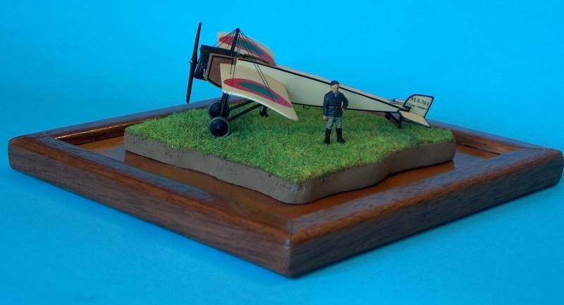
A Simple Story in Red and Green
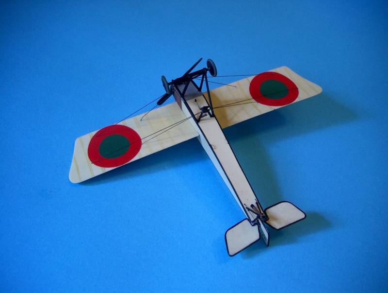
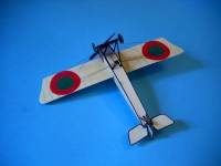
Scratchbuilding a Portuguese Morane-Saulnier Type H in 1/72nd
|
 |
The Aircraft
The History of Portuguese military aviation can be traced back to 1915
when construction works began for a pilot training school to be set up
at Vila Nova da Rainha, on the west bank of the Tagus some 50-km North
of Lisbon.
At its inception this school was equipped with the first two aircraft
that saw military use in Portugal: a Maurice Farman type 1911/12 and a
Deperdussin type B, but these were soon to be joined, in August 1916,
by a pair of Maurice Farman M.F.11 and later, on October the 1st, by a
somewhat disparate batch of aircraft that included five Farman F.40, two
Caudron G3 and a single Morane-Saulnier Type H.
 Humble
as this little monoplane might be, the Morane type H was already credited
with a quite interesting pedigree, this being mainly due to the achievements
of the famous French pioneer and works pilot Roland Garros, whose crossing
of the Alps and of the Mediterranean on an historic flight between San
Rafael in the South of France and Tunis imparted on the little single
seater monoplane an aura of ruggedness and reliability that would certainly
be one of the main reasons that led to the type and its twin seater counterpart,
the type G, being manufactured in quite interesting numbers, and being
adopted by several air forces. Humble
as this little monoplane might be, the Morane type H was already credited
with a quite interesting pedigree, this being mainly due to the achievements
of the famous French pioneer and works pilot Roland Garros, whose crossing
of the Alps and of the Mediterranean on an historic flight between San
Rafael in the South of France and Tunis imparted on the little single
seater monoplane an aura of ruggedness and reliability that would certainly
be one of the main reasons that led to the type and its twin seater counterpart,
the type G, being manufactured in quite interesting numbers, and being
adopted by several air forces.
Most of the type H aircraft were powered by the ubiquitous 80 hp Gnome
although a small series was to be motorized with a 6 cylinder 45 hp Anzani,
the single Portuguese aircraft being part of this batch.
In those days, production and design standardisation were of course
not as rigid as today and several design changes can be observed not only
in period photos but also in the few preserved aircraft of the type that
still exist, like the one at the Musée de l'air et de l'espace
at Le Bourget or the fantastic reconstructed aircraft of the Association
"Amicale Jean Batiste Salis".
 These
changes involve mainly undercarriage arrangement and the dimension and
shape of the front fuselage side access panels. This notwithstanding,
the Anzani powered machines had a totally different cowling arrangement,
in that there really was no cowling, so to speak…. (Confused? Blame
it on the writer who has trouble explaining some things in a tongue that
is not his own….). These
changes involve mainly undercarriage arrangement and the dimension and
shape of the front fuselage side access panels. This notwithstanding,
the Anzani powered machines had a totally different cowling arrangement,
in that there really was no cowling, so to speak…. (Confused? Blame
it on the writer who has trouble explaining some things in a tongue that
is not his own….).
In fact, the Anzani being a radial (the first double row radial engine
that ever was built) and not a rotary, there was no need for an elaborate
cowling to shield the pilot and plane from the hot oil and vapours spat
by the rotaries, hence the very simple metal panel on the forward top
of the fuselage and the nonexistence of the characteristic side cheeks,
that were to be seen on rotary powered aircraft.
The Model
 I
had never tried to scratchbuild an entire model before, but this seemed
like the perfect candidate due to its relative simple shape and also to
the fact that I would be able to borrow some more delicate parts from
the ICM Pfalz kit, (the Pfalz and Fokker E series also being a derivative
of the type H, but that's another story altogether) so after gathering
some references I fed my good luck handle a new n.11 blade and this is
how it went: I
had never tried to scratchbuild an entire model before, but this seemed
like the perfect candidate due to its relative simple shape and also to
the fact that I would be able to borrow some more delicate parts from
the ICM Pfalz kit, (the Pfalz and Fokker E series also being a derivative
of the type H, but that's another story altogether) so after gathering
some references I fed my good luck handle a new n.11 blade and this is
how it went:
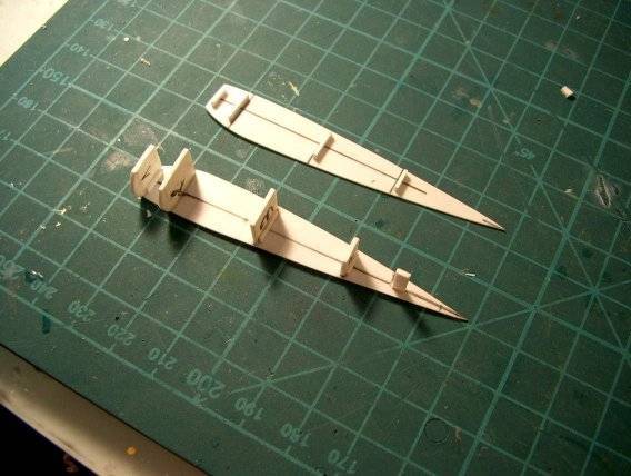
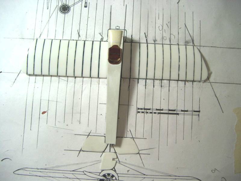
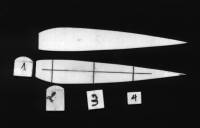
I started by cutting fuselage sides from sheet styrene (.5mm thick)
and to do this I traced the fuselage side onto tracing paper (do remember
to measure the length of the fuselage from the plan view or else your
fuselage will be a tad short, due to fuselage taper), and transferred
the contours to the sheet plastic by means of carbon paper (not something
easy to come by these days, I'm sure….).
 I
also cut 4 formers that were suitably reduced in size to compensate for
the thickness of the fuselage panels. The top section of the front formers
was round, so these had to be cut with the help of a compass cutter. I
also cut 4 formers that were suitably reduced in size to compensate for
the thickness of the fuselage panels. The top section of the front formers
was round, so these had to be cut with the help of a compass cutter.
I marked the location of the formers onto both fuselage sides and glued
them onto one of them, being careful to ensure that they sat at 90 º
in relation to the fuselage walls. To the back of each former I glued
some plastic strip to strengthen the joint.
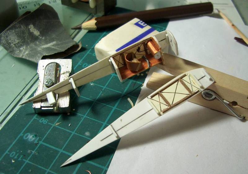
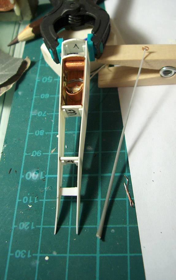
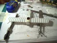
I now proceeded to detail the cockpit area: the structure was replicated
by means of very thin plastic strip, a floor was added, and the very prominent
fuel tank was easily fashioned out of a piece of sprue. I also made a
seat, a rudder bar, an engine throttle quadrant and a control column out
of bits of plastic, stretched sprue and fine wire.
 Seat
belts of masking tape with fine copper wire fittings were also added. Seat
belts of masking tape with fine copper wire fittings were also added.
The area was painted in CDL for the walls and the details were painted
in appropriate shades of wood and metal, as necessary.
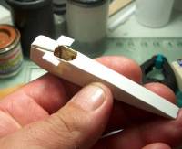
The fuselage sides were now glued together and set to dry for 24 hours.
To entirely close the fuselage I had now to add top and bottom panels:
remember I had cut the formers short to compensate for plastic thickness?
So now I overlaid the fuselage top and bottom 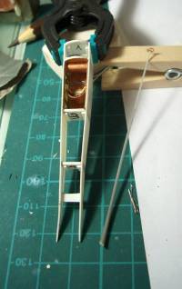 against
a piece of .5 sheet and traced the contours. Again discounting the thickness
of the fuselage sides (.5mm on each side) I cut top and bottom inserts
that were a snug fit between the fuselage sides, while resting of the
bottom and top of the formers. against
a piece of .5 sheet and traced the contours. Again discounting the thickness
of the fuselage sides (.5mm on each side) I cut top and bottom inserts
that were a snug fit between the fuselage sides, while resting of the
bottom and top of the formers.
The bottom insert was applied first and before gluing it in place I
rolled its front end around a cutter handle, in order to impart a slight
curvature to it, so that it would conform to the fuselage front upward
bend.
The top panel was applied from the rear of the cockpit to the fuselage
end and the full assembly was again set to rest for 24 hours.
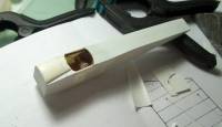
I now had a partially skinned, very strong fuselage box, Oversize pieces
of .2mm of plastic were now butt glued onto the top and bottom of the
fuselage, to ensure a perfect finish of these panels, making sure that
the top part had the correct cockpit cut-out.
Once fully dry I ran a new blade against the sides of the fuselage,
thus removing all the excess plastic from the panels, much as if I was
flash cleaning.
The fuselage was starting to look like it should, but there was still
work to be done on the section to the front of the cockpit, where two
round formers were now protruding.
 Initially
the plan was to overlay onto these formers a bit of rounded sheet plastic
and thus close the front fuselage, but on inspecting more carefully the
photos I came to the conclusion that the diameter of the curved sections
of the panels at windshield and front end level is different, i.e., at
windshield level the panel in not fully round, with flat lateral sections
tapering towards the front of the fuselage. Initially
the plan was to overlay onto these formers a bit of rounded sheet plastic
and thus close the front fuselage, but on inspecting more carefully the
photos I came to the conclusion that the diameter of the curved sections
of the panels at windshield and front end level is different, i.e., at
windshield level the panel in not fully round, with flat lateral sections
tapering towards the front of the fuselage.
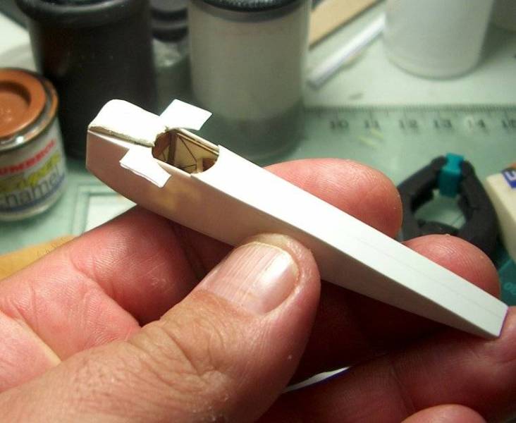
So I decided to go the easy way and first installed tiny triangles onto
the sides of the top front fuselage to replicate the "flats"
and the "hole" between the 2 formers was filled to overflow
with milliput and laid to rest for 24h.
The next day I carefully sanded and filled off the excess milliput (the
plastic formers acting as guides to know when to stop).
 The
fuselage was now done, and a good rub down with 800/1000/2000 'wet and
dry' used wet, took care of any imperfections that might have been. The
fuselage was now done, and a good rub down with 800/1000/2000 'wet and
dry' used wet, took care of any imperfections that might have been.
I now turned to the wings.
These started as a strip of 1-mm (well, about that thick… I didn't
measure) plastic cut from one of those boards used to advertise movies,
that used to be in card when I was a kid but lately appear to have succumbed
to plastic ubiquity.
The oversize strip was cambered using the Woodman method: the front
and rear edges of the strip were clamped down to a piece of board, after
laying it over a thin strip of balsa longer than the span of the plastic
strip. The balsa strip was located at about 1/3 the cord of the plastic
what imparted a nice airfoil curvature to the plastic. The whole cambering
jig was inserted into boiling water and let inside for a few seconds,
after which it was passed under running water. Once the clamps removed
I was left with a cambered strip from which I cut the 2 wing blanks .
 Although
curved the blanks still needed to be given a correct airfoil profile,
and this was created through sanding the top and bottom sides of the wings
from 1/3 chord down to the trailing edge. Although
curved the blanks still needed to be given a correct airfoil profile,
and this was created through sanding the top and bottom sides of the wings
from 1/3 chord down to the trailing edge.
When I was fully satisfied with the profile and contour of the wings
I again gave them a rub down with 800/1000/2000 wet and dry to eliminate
any scratches.
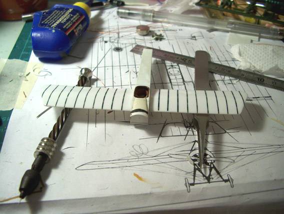
Ribs had now to be instated and to do this I applied thin strips of
dark decal at each rib location. I used some leftover Americal Gryphon
decals, because they are quite thick and help achieve the desired effect.
Once the decals were absolutely dry I applied 2 or 3 coats of future
with a soft brush. The future built up along the decal strips imparting
a very nice scale rendition of rib/rib tape effect.
 On
the underside of the wings I elected to pencil in the rib tapes. In fact
if you look closely at the underside of a fabric covered wing it is almost
flat with very slight depressions at each rib station, not the convex
"hill" that is usually depicted on kit parts. On
the underside of the wings I elected to pencil in the rib tapes. In fact
if you look closely at the underside of a fabric covered wing it is almost
flat with very slight depressions at each rib station, not the convex
"hill" that is usually depicted on kit parts.
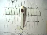
The wings were to be butt joined to the fuselage but I was afraid that
I might misalign them not only in relation to each other but also in relation
to their location in the fuselage sides, so I carefully made holes on
the thin sides of each wings as close as I could to the LE and TE into
which I inserted copper wire pins. I made corresponding holes in the fuselage
sides and hoping I had done it all well I glued the wings onto the fuselage
sides with Revell "Contacta" glue. Liquid glue was then ran
along the joint and this ensured a very strong bond.
All that was left now was the very small panel that shields the top
of the engine, and this was done in 3 parts: a short curved strip for
the top section, butt joined to the fuselage front and 2 small triangles
for the sides. A touch of putty here and there and some CA from the inside
to reinforce the joints and it was done.
I now made all the rigging holes with a .3mm bit and also locating holes
for the pylons and the u/c, these being adapted parts from ICM's Pfalz
EIV kit.
 The
model was given a couple of coats of CDL mixed out of Dyrup and Robiallac
household enamels (white, brown and yellow). The wood section of the front
fuselage was done with my usual wood recipe (Humbrol 63 base coat and
watercolour pencil grain) and the black panels were painted in Robiallac
black. The
model was given a couple of coats of CDL mixed out of Dyrup and Robiallac
household enamels (white, brown and yellow). The wood section of the front
fuselage was done with my usual wood recipe (Humbrol 63 base coat and
watercolour pencil grain) and the black panels were painted in Robiallac
black.
After the paint had dried the ribs on the upper side of the wing were
slightly accentuated by means of light strokes of watercolour pencil while
on the underside they were pencilled in, by drawing parallel lines with
a contrasting colour (brownish hue) at the rib locations. Simple and,
to my eye, effective.
The black lining on the fuselage was added by means of black painted
strips of decal, cut with 2 blades held together, to ensure constant thickness.
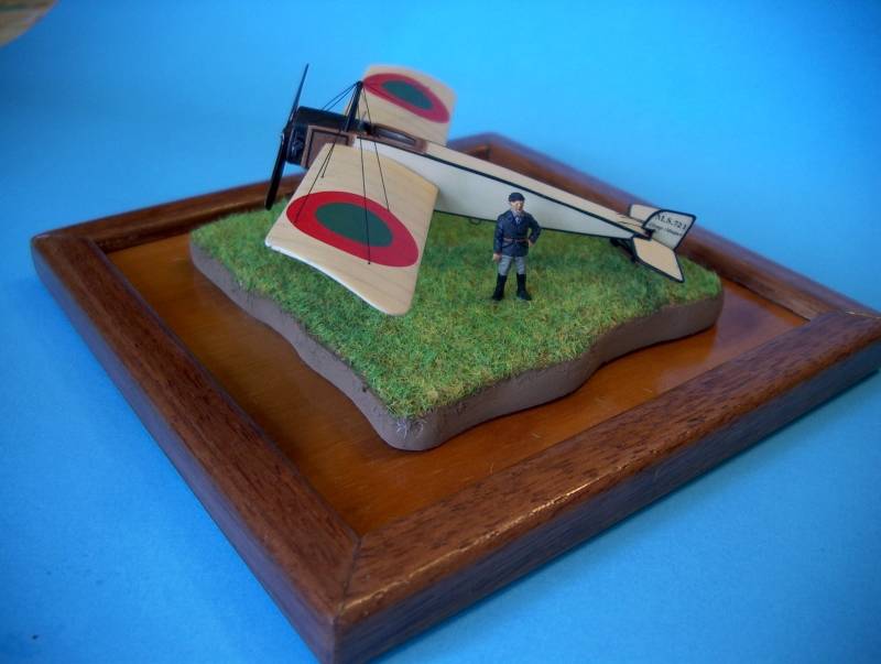
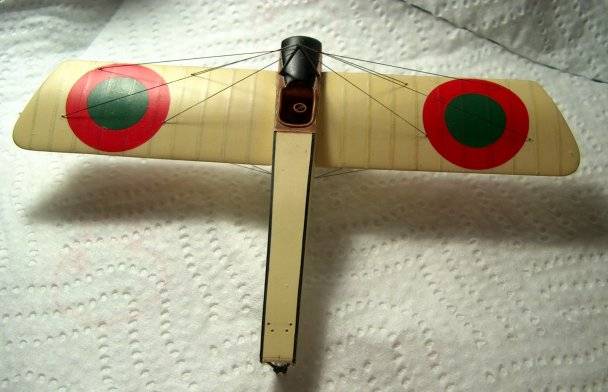
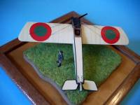
I now needed to add the distinctive Portuguese cocardes and these were
done by superimposing concentric circles cut from green and red painted
decal sheet. As usual I used Kleer as decaling/setting solution and once
fully dry the results were quite satisfying.
 I
assembled the rather complicated undercarriage from the Pfalz kit, painted
it black and offered it to the pre-drilled holes in the fuselage, securing
it all in place with drops of CA. I
assembled the rather complicated undercarriage from the Pfalz kit, painted
it black and offered it to the pre-drilled holes in the fuselage, securing
it all in place with drops of CA.
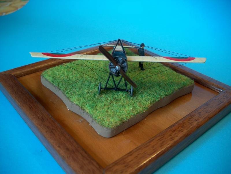
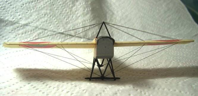
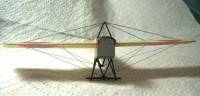
The upper and lower pylons were also installed in pre-drilled holes
at the correct locations and I proceeded to rig the aircraft with invisible
thread painted black with a permanent marker.
Since 4 wires attach at the lower pylon while the other 4 terminate
at the front section of the u/c I could not use just 2 long pieces of
wire for all the bracing. I ended up using 4 pieces, each one running
from the lower pylon through the wing, through the upper pylon, through
the wing again, into the front u/c.
The decals for the rudder with the words MS721 "Charge Maxima",
were laser printed onto clear decal and applied to the rudder (this was
quite difficult since the decals were small and fragile and tended to
curl once out of the backing paper (luckily I had done several sets, just
in case… so I had more than one try).
 The
wheels and tailskid were also placed in their correct locations and all
that was missing now was the engine and prop. The latter wasn't problematic,
since again the ICM Pfalz item could be used, but the former was quite
a different matter since the Anzani engine was a 6-cylinder block and
I had nothing resembling it in the spares box. The
wheels and tailskid were also placed in their correct locations and all
that was missing now was the engine and prop. The latter wasn't problematic,
since again the ICM Pfalz item could be used, but the former was quite
a different matter since the Anzani engine was a 6-cylinder block and
I had nothing resembling it in the spares box.
So the solution was to scratchbuild one, using a method I pinched from
Maestro Alberto Casirati: each cylinder was made from thin copper wire
wrapped tightly around plastic rod and secured with CA. I drilled holes
at the base of each cylinder to insert a pin that was then inserted into
a corresponding hole in a section of hollow plastic tubing, this being
the crankcase of the engine. Two different sized circles of sheet plastic
were then glued onto this hollow tube section and the engine was done.
After painting it does look good, if not 100% accurate, but as long as
it looks the part it is ok for me.
 The
semi circular exhausts were fashioned out of telephone wire and painted
a rusty colour. The
semi circular exhausts were fashioned out of telephone wire and painted
a rusty colour.
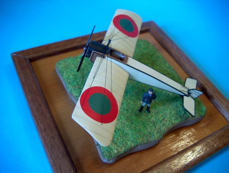
The engine was then placed in its intended location and the propeller
glued in.
A final coat of semi-matt varnish evened out the different sheens from
the wax and paints.
Conclusion
I had a great time with this model and for a first scratch built project
I have to say that I was quite happy with the results. Of course this
was an easy one: slab sided fuselage, almost no curves, simple shapes,
etc, but I learned a great deal while doing it and I really think I've
climbed another step in the learning stairway.
 As
usual, a lot of people were quite helpful not only with references for
the project (and here I have to point out the people at the Aviation Hobby
Site, a Portuguese aviation nut forum, - aviation-hobby-site.com - especially
Fernando Correia, Fernando Moreira, Luis Dias and Miguel Ribeiro, who
promptly showed me photos that helped clear some doubts I had about a
somewhat obscure aircraft). As
usual, a lot of people were quite helpful not only with references for
the project (and here I have to point out the people at the Aviation Hobby
Site, a Portuguese aviation nut forum, - aviation-hobby-site.com - especially
Fernando Correia, Fernando Moreira, Luis Dias and Miguel Ribeiro, who
promptly showed me photos that helped clear some doubts I had about a
somewhat obscure aircraft).
Also the usual bunch of friends at the WW1 Modeling Mailing List, of
the WW1 Modeling Site, was also
very helpful in their constructive criticism and encouragement, for which
I thank them all.
As a final note I can but recommend anyone never having tried this approach
to modelling to go and try it by themselves. More than anything, it is
fun and rewarding, and you cannot ask for more from your hobby, can you?
References
Os Aviões da Cruz de Cristo - Lopes, Mario Canongia and Costa,
José Manuel Rodrigues, Dinalivro, Lisboa, 1989.
French Aircraft of the First World War - Davilla, Dr. James J. and Soltan,
Arthur M., Flying Machines Press, Stratford, Connecticut, 1997.
Pfalz Aircraft of World War I - Herris, Jack, Flying Machines Press,
Boulder Colorado, 2001.
|


|