Blue Max 1/48 Junkers D.I
By David Calhoun
 |
History
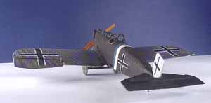
The Junkers D.I was a revolutionary all-metal monoplane designed by Professor Hugo Junkers during World War 1. It arrived at the front too late to influence the outcome of the war, but in a period of fabric and wood biplanes the D.I showed what was to come in the future.
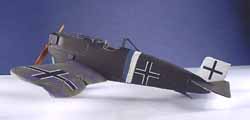 Junkers had experimented for several years on a metal monoplane with a thick cantilevered wing. He used corrugated duraluminum to cover the all metal airframe. This metal was much lighter than steel and much work was needed to assemble the metal aircraft. Several test versions were made, with the J.9 being the final version. This was the prototype for the D.I. It was powered by the Mercedes D.IIIau 160hp engine, and armed with twin Spandau machine guns. There were a total of 40 D.Is built between June 1918 and February 1919 when production stopped. It is not known if any served in combat before November 1918, but the D.I saw operational service in 1919 fighting invading Bolshevik forces in Poland and the Baltic countries. The metal construction made them well liked, and able to withstand the severe weather in this region.
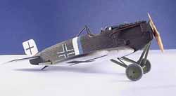 There were two major variants of the D.I built, the first production version had a long tail, but due to instability in the air, a shorter tail was produced on later versions. In January 1919 four D.Is were found by Allied Armistice inspection teams. One of these aircraft was decorated with a two color band behind the cockpit - this is the plane that I chose to model. References for this aircraft came from the front cover painting and two photos in Windsock Datafile 33. This book is the best single reference that I have seen on the Junkers D.I, and includes scale drawings and many detailed interior drawings and good detail photos.
The Kit
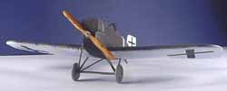 The Junkers D.I has been kitted by at least three manufacturers in 1/48 scale, and at this time none are still in production. Lone Star Models did a nice resin kit, and Czechmasters also did one in resin. The Blue Max limited run kit is the only one produced in styrene. The kit was a short run kit, limited to 1500 numbered copies. It was released in 1990, and I was able to get one about 10 years ago after viewing a built up kit at my local model club. Unfortunately they are no longer available. They frequently appear on eBay but command high prices. The overall kit is nicely molded, but like most limited run kits needs a lot of work to remove the sprues and get a nice fit. It is molded in dark gray styrene. Also included are a bag of white metal parts and a sheet of decals.
Engine
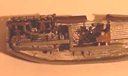 Assembly started with the 160hp Mercedes engine, which consists of plastic halves with metal detail parts. After assembling the engine you must cut off everything below the engine bearers to get it to fit into the fuselage. A Dremel tool with small grinder is great for this. Then cement the engine bearers to the engine. I added ignition wires, six on each side. A rod of Evergreen styrene was painted red and cut to length - this represents the tubes that hold the ignition wires. The wires run from holes in the tubes to the spark plug on the real engine. I super glued thin copper wire painted light gray to represent these wires. A good photo of this engine appears in the book Albatros DVa by Robert Mikesh on page 52.
The cylinders should be painted black, the crank case aluminum and all other parts steel. Note: after assembling the fuselage halves and adding the gun troughs, the left hand side of the engine is not at all visible, and the right hand side is obscured by the exhaust pipe. You may want to just add the wires to the right hand side, as the red pipe is visible through the exhaust area, and adds some very bright detail to the engine compartment.
The finished engine was given a wash of oily black to look used, and set aside.
Wings
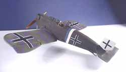 The wings were the next problem that I tackled. The main problem with the wings is a very thick trailing edge. There are also very thick sprue attachment points, these are best cut off with a razor saw and sanded smooth with a sanding stick. The upper wing was sanded flat using a sheet of wet/dry sandpaper much like doing a vacuform wing. The lower wing needed even more material sanded off. After hours of sanding I was able to get a nice thin trailing edge. I used a razor saw to cut off the ailerons, and cemented them together. There was a step between the upper and lower wing, so I filed an angle to get them together in a straight line. I used liquid cement to attach upper and lower wing halves and clamped them with clothespins to dry.
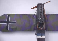 Be sure the corrugations on the leading and trailing edge line up correctly, there is no way to fix them if they are out of line. Once dry, a knife edge modeler's file was used to clean up between the corrugations on the leading edge. The color break is on this line, so minor variations won't kill you here. The ailerons were attached in a deflected position, the left going down and the right going up. A small lever was attached to the top of the ailerons and a wire linkage was attached with super glue.
Interior and Fuselage
The interior was started next. I began by cleaning both fuselage halves and sanding them like the wings to get a good fit. The walls of the fuselage were too thick and did not have any interior detail molded in, so I sanded them thinner. The interior should be corrugated, the opposite of the outside surface. To get a realistic interior I scribed the corrugations into the interior using a scribing tool.
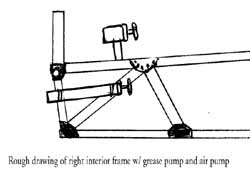 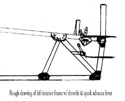  |
I used thin Evergreen strips to represent the interior structure. This is shown well in the Datafile. A throttle lever and spark advance lever were made from styrene and wire and added to the left hand frame. The right side had a grease pump and fuel pump made from styrene tubes with wire handles.
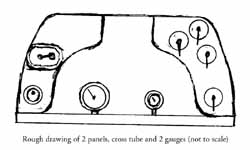
The instrument panel provided in the kit is incorrect, it has a large panel with three gauges on the decal sheet. According to the Datafile, there should be two small panels, one on each side of the fuselage. The center is open, and a tube connects both sides. Two gauges are attached to the tube. The panel on the left side has a starting magneto and a silver switch on it. The right hand panel has four fuel cocks, similar to the Albatros D series layout. I scratchbuilt both panels from sheet styrene, with a magneto and the fuel cocks taken from an Eduard Albatros D.V kit.
The kit supplied rudder pedals and control column did not match the parts supplied in the kit. The control stick in the kit resembles a Pfalz type, while drawings in the Datafile show the Fokker style stick. I used a stick from a Dragon Fokker Dr.1, and added handles for the fuel control and wires for the guns and throttle. The floor had two strips of styrene attached to support the seat, and photoetched rudder pedals were added. rudder cables were added with stainless steel from a DML kit. These two wires run from the rudder pedals under the seat to the rear of the plane, so I glued them to the seat supports, then glued the seat in place. The seat was replaced with an Atlee Models Albatros D.V resin seat, which had a well detailed harness molded in. I waited until final assembly to add the tube with the gauges and the control column.
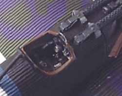 I added the engine to the right hand side of the fuselage, making sure that the exhaust cleared the cut out in the cowling. The fire wall was glued in, and the interior floor was glued to the firewall and fuselage side. The panel that holds the guns was difficult to fit in correctly, I trimmed off the blast tubes and added them later. Gap filling super glue held the gun mount in position. The fuselage was then glued together, making sure to get a clean edge on the top, since the corrugated metal could not be sanded and filled.
The bottom had a slight step, so I sanded it as smooth as possible without damaging too much of the corrugations, then rescribed in the corrugations. I also added two small panels under the engine as seen in the Datafile, and scribed corrugations into these hatches. The rear tailskid was then attached.
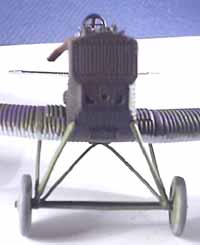 The radiator was added, and I drilled out the two small intake openings on either side of the prop shaft. I left the shutters closed as molded, but some photos show these panels open similar to the ones on a SPAD.
Further fuselage details were added after painting, but the horizontal stabilizer had to be added at this time. This had a very thick trailing edge, and I sanded it down to a scale thickness. I lost some of the corrugations, but they were easy to scribe in. I cut the control surfaces and repositioned them to match the photo in the Datafile. There was a large gap where the tail attached to the fuselage, but this may have been because I trimmed too much away trying to get it to fit correctly. There are no location marks for the tailplane, so you must sand and fit until you get a good fit. Some putty was needed to get it to fit correctly.
Painting
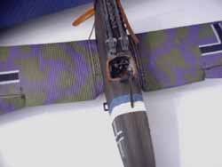 At this point I was ready to begin painting. I covered the fuselage with a coat of white primer. I masked off the area of the white band. At this time, I discovered that the plane in the photos was a long tail variant, but the kit was a short tail. Oh well, after this much work I was not going to change my mind. I sprayed a blue stripe on the fuselage using Model Master German Dunkleblau (24) which is close to the color of Bavarian blue. The blue in the photo looked almost as dark as the brown fuselage, and the light blue on the cover painting seemed too light.
After masking off the blue, I mixed up the under surface color, a bluish white. I mixed a little bit of the Dunkleblau in a bottle of white just to give it a light tint. It should not be turquoise as shown in the instructions. Paint the underside of the horizontal tail and both wings this color. After it dried, I masked off the undersides, and added the metal grab handles and step to the fuselage in predrilled holes.
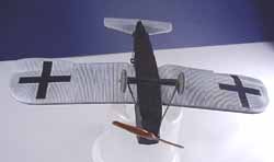 The entire fuselage was then painted the dark brown. I used Testors rubber for this color. After this had dried, I pulled off my masking tape on the fuselage bands. What a disaster! The brown paint creeped under the corrugations and got on the colors underneath. A sharp brush was used to meticulously touch up the edge between the corrugations.
After all was dry, I gave the fuselage a couple of coats of Future to prepare it for decals. I also painted the wings at this time - I used Silly Putty (the kind the kids get in a plastic egg) and rolled out a string about 1/4" thick. I ran it along the leading edge to cover up the white underside. A little pressure allows the putty to bend into all of the corrugations, giving a sharp edge. I then painted the upper surfaces a light green by Polly S. The camouflage was airbrushed on using Polly S violet. The pattern was done by looking at the photos in the Datafile, and a little imagination. I touched up any rough edges with a brush, and removed the silly putty.
Wing to Fuselage Assembly
 To finish up the assembly, the wings must be attached. Sand the edges and test fit to the fuselage, making sure both sides fit squarely against the fuselage. Scrape the paint off of the fuselage, and glue the wings on with liquid cement. Make sure the wings are square, and the wing tips are up the same distance on both sides. A pencil under both wing tips will give the proper dihedral. When dry, you can add the fuselage details. There are hand holds on either side of the rear fuselage and a foot step made of white metal. Holes are drilled for these and they are super glued in place.
The pilot's roll bar is next - add a cross brace from stretched sprue, paint it brown and glue it in place. Spray an overall coat of future to prepare for decals.
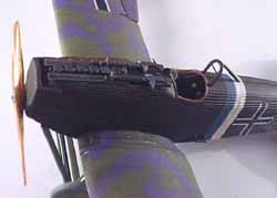 At this point I noticed that the rudder was missing! An e-mail to the guys on the World War One mailing list provided me with a resin copy made from John Cyganowski's own rudder! I painted the rudder gloss white to prepare for decals. I drilled a hole in the bottom of the rudder, and added a brass rod for the rudder support. Looking at photos, the rudder is not attached to the fuselage, the pivot rod goes into a hole in the fuselage leaving a gap between the rudder and fuselage. I drilled a hole into the fuselage where the rod went, and after final painting I pressed the rudder into the hole.
Decals
I used Americal Gryphon decals - sheet No. 34 - Spatere Balkenkreuz 1918. These are the narrow black cross. I applied the decals to the wing, fuselage and rudder. I tried using Microsol to get them to sink into the corrugations, with not much luck. I also tried Solvaset, which is said to be much stronger than the Microsol. Still no luck. I ended up slitting the crosses in between each rib, Solvasetting them again, and touching it up with black paint applied with a thin brush. A coat of Future sealed everything in and I was ready for the final assembly.
Final Assembly
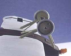 The meeting point. I stuck the struts into a block of styrofoam, trying to get the correct angles and spacing. The spreader bar was glued in position with super glue. It was then glued to the holes in the wing and fuselage. It took a couple of trys, the struts kept popping out when bent to the correct position, but when finally all in straight I superglued all struts at both ends for a tight fit. Make sure the undercarrage is level or the wing tips will not be a even distance from the ground. To finish the landing gear, a V shaped strut is glued into place. This strut looks over size compared to the Datafile, but I kept it to strengthen the undercarrage.
At this point I mixed up a dull coat consisting of Future mixed with Tamiya flat base - about 30% flat base to 70% Future. This gave a good overall flat surface.
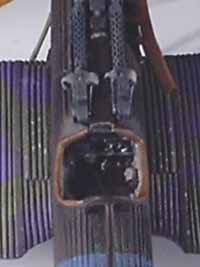 The kit guns were replaced - they looked too thin. I used DML Fokker Dr.1 guns with some brass jackets, sights and cocking levers that I had in my scrap box. I believe that they came with the Koster Fokker D.VIII kit. The guns were painted using my three step process, a base coat of Model Master gunship gray, then a heavy wash of black, and a drybrushing of steel. To finish up the guns I scraped some pencil lead on a piece of sand paper, and brushed this over the guns to give it a metallic sheen. The flash guards were then super glued to the top of the engine, attached to the side of the cam boxes and the gun support area. The guns were then super glued into position. Black pastel was used on the ends of the barrels and on the flash guards.
At this point I added the cross tube made from Evergreen rod underneath the two instrument panels. This tube appears to hold two gauges, one large and one small. (The photo in the Datafile only shows these two but the right side is cut off.)
There may have been more than two, but I have no evidence, and only added two gauges. I took gauges from Copper State Models German gauge set - one of the smallest gauges and one of the larger ones. I painted the back of the gauges white, and attached them to styrene rods. I painted the rods steel, then attached the gauge bezels to the gauge with Testors gloss laquer. This dries crystal clear and looks like the glass of the gauge. Then I trimmed the rods to the correct length and super glued them to the cross tube. To finish it up, I cut a rectangle of clear styrene and rounded the corners to represent the windshield. This was glued in place with Elmer's white glue.
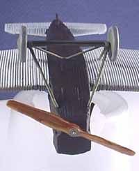 To complete the model. I used a black wash over the radiators, panel lines and walkway on the wing. Some Testors aluminum was used to add small chips to the leading edges of the wings, tailplane and walkways. The final detail was to add a wooden propeller made by Martin Digmayer. These are beautifully laminated, hand carved and finished with a clear gloss varnish. They are available in the US from Copper State Models. I drilled a hole through the prop, added a photetched boss from Copper State Models, and super glued a brass rod in place. It was then pushed into the hole drilled in the radiator. Per all of the photos in the Datafile, there were no prop logos applied to the props on the D.I.
Conclusion
This was a tough kit due to fit problems and the corrugated surface, but it was nothing that a little time couldn't take care of. The aircraft looks oversimplified standing next to a shelf full of Albatros and Fokkers, but it is a historically important plane, and I am proud to add it to my collection of German World War 1 aircraft.
References
-
Junkers D.I Windsock Datafile 33 by Peter M. Grosz 1992
-
Albatros D.Va German Fighter of World War I by Robert C. Mikesh 1980
