Introduction
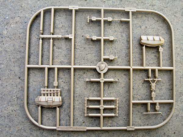
Kit parts
Colours
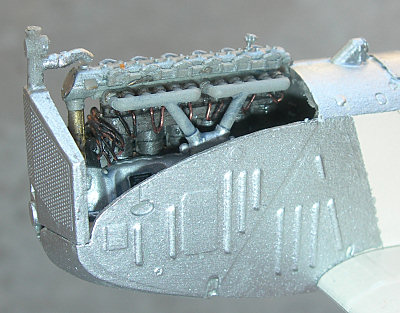
Build Steps
2. Add the PE labels and gaskets, if applicable.
3. Add the magneto assembly, parts X2 and X10(2). Not that the magnetos are supposed to be at an angle of 104º to each other, and not 90º. A right angle will cause you some problems with later fittings.
4. Additional scratch building step - Add HT cabled to the spark plugs and
5. Add the air pump, X6 and the carburettor, X12, and the PE plate 13 if applicable.
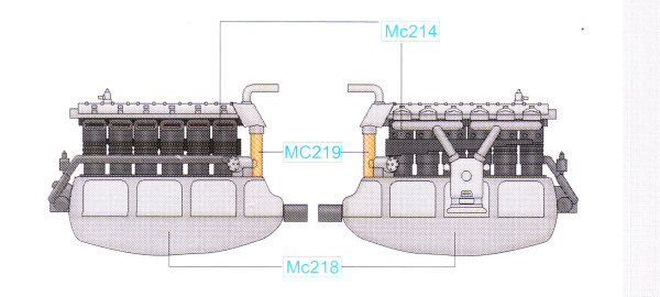
6. Add the cooling system to the engine block and the cylinder cooling jackets. X7, 3, 13. NB the exploded view in the instructions may showX5 and X3 incorrectly postioned. Part X3 should be above part X5, as in the diagram shown here.
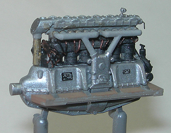
Detailing
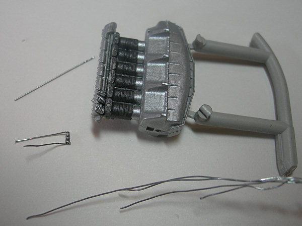
I was able to add some copper wire as HT leads to the spark plugs, ans to the magnetoes. I also experimented with adding valve springs, which should be manageable in scale, but my attempts weren't as precise as I wanted. See for yourself in the image above.
Conclusion
Thanks
Thanks to Eduard for the kit. Thanks to Karen Rychlewski for permission to use her images of the engine at the Krakow Museum.
References
Flight Magazine October 31 1918 p 1217-1222
Flight Magazine November 7, 1918, p 1255-1259
Flight Magazine; November 14 1918, 1 1288-1293
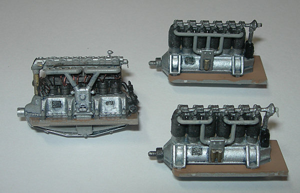
Karen Rychlewski's photos of the engine the Kraków museum.
Andi Szekeres' photos of the engine at the Budapest Aviation Museum/Vienna Technical Museum.