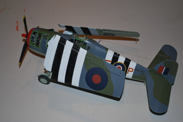
Trumpeter 1/32 Grumman F6F-3 Hellcat
By John Newcome
Background
The Grumman F6F Hellcat was the successor to the F4F Wildcat. Design of the Hellcat was initiated in mid-1941. The Hellcat was armed with six 50 caliber machine guns and was also able to carry additional ordinance under the wings. The Hellcat also served with US allies which were supplied under the Lend Lease program.
The British Fleet Air Arm operated 252 F6F-3s and approximately 900 later F6F variants. In British service the F6F-3s were initially known as Gannets. The designation was later changed to Hellcat. In 1944 the station at Lee-on-Solent, southwest of London on the Channel coast, served as a base for air support for the invasion of Normandy. Several Fleet Air Arm squadrons were attached to RAF Coastal Command at this time and operated both by day and by night missions over the English Channel.
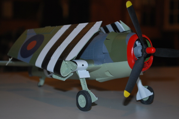
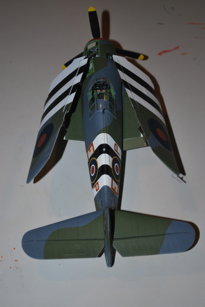
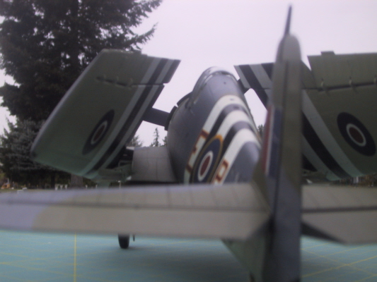
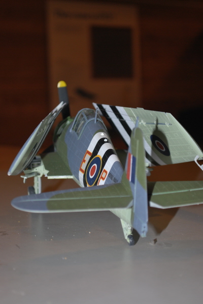
The subject model of this article represents a Dutch Hellcat of No. 860 squadron which provided air support for the invasion of Normandy.
The Kit
This kit consists of 400 parts molded on 9 sprues of gray styrene and 1 clear sprue. The major clear parts include the cockpit windshield, canopy and cowling.
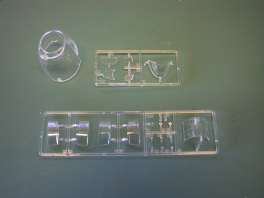
There are also some excellent aftermarket resin and photo etch sets available for the Trumpeter Hellcat kit.
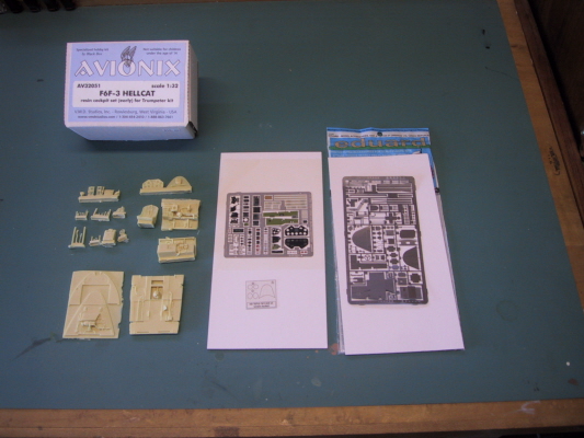
Cockpit
The cockpit is made up of 35 well-molded gray styrene parts which assemble without issue. However, it is fairly generic and to my eye begs for some scratch building or aftermarket resin and photo etch. I used this as an opportunity to do just that and incorporated additional detail from Avionix resin set and the Eduard photo etch set.
According to my references, the resin seat is more accurate than the kit seat. Nevertheless, I elected to use the kit seat for this build so I could incorporate painted photo etch seatbelts from the Eduard set. The instrument openings in the resin part do not line up with the instrument film from the Trumpeter kit. I little fiddling is necessary with the clear film in order to get all of the instruments to line up. The kit instrument panel is molded in clear styrene with molded in lenses. I ended up using the kit part and drilled out the lenses so that the instrument dials would appear recessed slightly.
The only real issue I have with the cockpit is that the rear bulkhead is from the F6F-5 variant and lacks the rounded cutouts on each side immediately in front of the rear window. This is easily accomplished with some careful cutting and filing. One other nit pick relates to the pedestal below the instrument panel which houses the gun charging controls. It is set too far back under the instrument panel. My references indicate that the pedestal should be slightly forward from the front of the instrument panel. Moving it forward interferes with the control stick and seat. Therefore, I took the easy road I elected to live with it as designed.
Engine
The engine is a model in and of itself of the P&W R-2800.
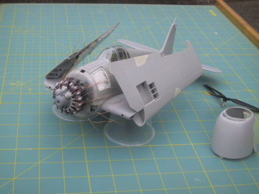
Trumpeter also did not provide the baffle that fits between the cylinder banks. I fabricated a baffle ring out of out of the round sprue that held the valve rods. It helps make the gap between the cylinder banks somewhat less noticeable.
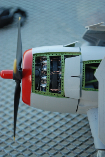
An additional issue with the engine is that the exhaust piping to the front cylinders does not quite reach the cylinders. To address this I added short lengths of appropriate diameter styrene rod to the end of each pipe and enlarged the mating hole in the cylinders. After assembling the engine, it may be a good idea to skip ahead to steps 20-23 of the instructions to identify and plan for the additional exhaust piping that is required. Based on my experience with this build, I recommend that the additional exhaust piping be installed at this stage before closing up the fuselage and gluing the engine to the firewall.
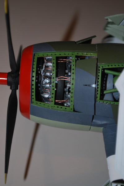
Despite the issues mentioned, the engine and the accessory compartment have a wealth of detail and are worth detailing and displaying. To display the engine, the modeler is faced with a couple of choices: use the clear cowling as provided or open up an access panel. I have never seen a Hellcat or any warbird for that matter with clear cowling so I decided to open up an access panels on the cowling and another over the accessory compartment. Opening up the access panels of the cowling also gave me an opportunity add some additional detailing to the inside surfaces and appease the AMS gods. If you decide to open up an accessory panel check your references carefully. There are many parts, such as the ductwork, that are not provided in the kit. I also added bits of styrene rod and copper wire here and there to represent the ignition wires.
Fuselage
The F6F-3 version had a window behind the cockpit. Constructing the Trumpeter F6F-3 version requires opening up this window using a guide molded into the interior of the fuselage halves. While the molded in outline of the window appears to accurately match references, the shape of the clear window parts do not fit this opening as I expected. Perhaps this may have been due to me not cutting out the opening accurately. However, to my eye the corners the windows provided by Trumpeter are too sharp and do not match my reference photographs accurately. I was able to modify the shape of the clear parts sufficiently with files to get and adequate but not perfect fit. An alternative would be to scratch build the windows using clear styrene from a CD case. From the modeler's perspective would have been much easier if Trumpeter molded the fuselage with the window openings and provide two inserts; one in clear styrene for the F6F-3 version and one in solid styrene for the F6F-5 version. I realize that this may not be reasonable since F6F-5 kit was released first and there were more variants of the Hellcat without this cockpit window than there are with it.
Camouflage and Markings
The kit provides markings for two aircraft. Medal of Honor recipient David McCampbell's "The Minsi" and Alex Verau's number "19". Both of these aircraft have the Navy tri-color scheme. The decals provided in the kit appear to be well printed.
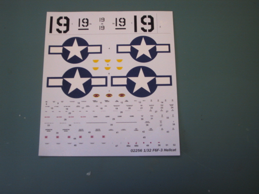
After some additional research and conversations with Chris Benye Reipl, I decided to build this kit in the markings of the Fleet Air Arm Hellcat was attached to the RAF Coastal Command as support for the D-Day invasion of Normandy. This model represents an aircraft from Dutch number 860 squadron. The camouflage was painting using Tamiya and Polyscale Acrylics. The upper surfaces are done using Polyscale Dark Sea Grey and Dark Slate Grey. These are a match for the official colors of ANA 603 Extra Dark Sea Grey (Sea Gray) and ANA 613 Dark Slate Grey (Olive Drab). The lower surfaces are done using Tamiya Sky (ANA 610).
Finding appropriate decals for the markings turned out to be a challenge. After a considerable search, I finally located the markings in a set produced by a company in the Netherlands called Dutch Profile. They are sold through several distributors world wide. I purchased mine from FlightDecs in Ontario, Canada. Their web site is included in the references below. They carry complete assortment military decal sheets from a variety of manufacturers. The alternative which I was seriously considering was to make my own decals and masks. The decals are well printed and in register. They are also extremely thin which caused some of the Invasion stripes to show through. There was some slight silvering on the roundels despite applying a light coat of Future acrylic as a base for the decals. I attribute the silvering to my less than perfect decaling technique rather than the decals themselves. I'm thankful I found this decal sheet for I surely would have made a mess out of making my own markings.
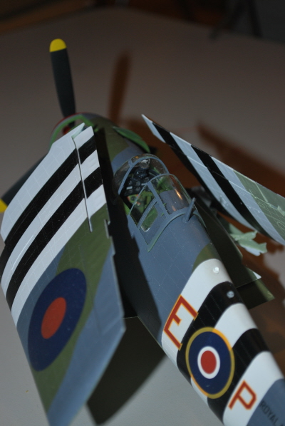
AMS has really kicked in now. I've attempted modifications to the open access panels in the engine and accessory compartment and the additional detailing required to justify it. Plus I'm doing a scheme not intended by the kit manufacturer. Aircraft modeling surly does not get any better than this.
Wings
Trumpeter provides the modeler with a choice of positioning the wings extended in flight position for folded aft. Separate brackets are provided for the extended and folded wings. The folding mechanism is not operable. I elected the folded wing option because I do not have any aircraft in my collection with folded wings. The folded wings also save space for display.
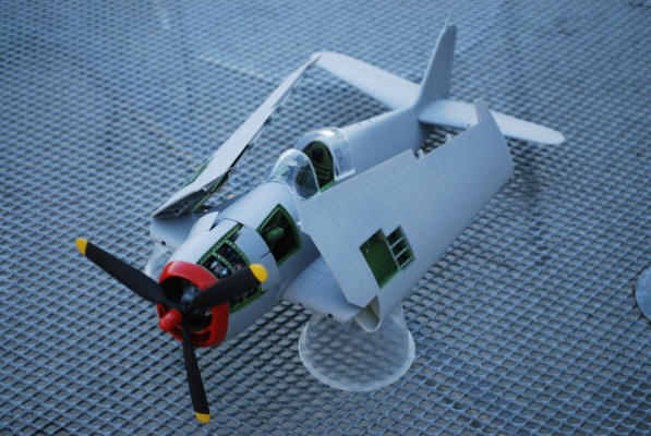
There are also well molded and detailed gun bays in the wings. They are complete with six .50 caliber machine guns and ammunition feeds. The gun bay doors are separately molded so they can be displayed open or closed or removed.
All of the flight control surfaces are molded separately. The flaps, ailerons, elevators, and rudder can be positioned any way the modeler chooses. However, one of my references indicated that the Hellcat had spring loaded control surfaces which returned them to the neutral position when the stick and rudder pedals were not in use. This kind of defeats the advantage of separate control surfaces for posing them in various positions. You may want to check your references on this issue.
The kit also provides a full compliment of external ordinance including options for under wing rockets, inboard bomb racks with bombs. A centerline fuel tank is also provided.
Landing Gear
The landing gear is designed to be displayed in the down position only. The landing gear locking mechanism is molded in the down position. This prevents the gear door from being installed in the closed position. Removal of the locking hook allows the gear to be positioned in the retracted position. The tires in the kit are molded in black vinyl and represent the thin high pressure tires used in carrier operations. However the tires are too narrow to accommodate the depth of the wheels. The solutions are to purchase appropriate aftermarket resin wheels, rob the wheels from another kit you have in your stash or modify the kit provided parts. I was able to achieve an acceptable result by carefully sanding down the back of each wheel about 1/16 inch per wheel half. I also sanded the back of the outer rim both wheel halves until I had a reasonable fit. A brief word about the tail wheel is in order. The design of the tail wheel strut and shock absorbers is extremely fragile. The instructions have the modeler install it early in the build when the fuselage halves are put together. The parts are sandwiched between the fuselage halves. I managed to break it several times. If I were to do it again, I would modify the attachment and install the tail wheel at the end of the build and maybe strengthen the whole assembly with wire.
Conclusions and Recommendations
This kit builds into a fine representation of the Hellcat out of the box. In the hands of an experienced modeler, it provides an excellent basis for some scratch building and superdetailing. Except for the incorrect printing of the decals, none of the issues mentioned in this article cannot be fixed with a little effort. Overall, the engineering and parts fit of this kit is excellent. This has been the first Trumpeter kit I have built. Although I normally do not model in 1/32 scale, I have eye on the Trumpeter TBM Avenger or the F4U Corsair to add to my collection. I highly recommend this kit to anyone who is looking to build a large scale Hellcat they can be proud of.
Thanks to Chris Banyai-Riepl and Internet Modeler for providing this kit, and for their exceptional patience in waiting for me to complete this build. I'm also thankful for his insight into the Hellcat FAA camouflage scheme. Thanks to Emil at Skyway Model Shop for ordering the Avionix resin and Eduard photo etch sets. And finally, thanks to Neil Makar, at the Northwest Scale Modelers group for taking several of the photos for this article.
References
F6F Hellcat in detail and scale vol. 49, Bert Kinzey, Squadron Signal Publications.
The British Fleet Air Arm in World War II, Mark Barber, Osprey Publishing
Fleet Air Arm Archive
JPS Modell website, Don Color camouflage colors.
Aftermarket Suppliers
Dutch Profie - Decal sheet number DDPD0632
FlightDecs - decals
Avionix - resin cockpit set
Eduard Model Accessories - photoetch parts

