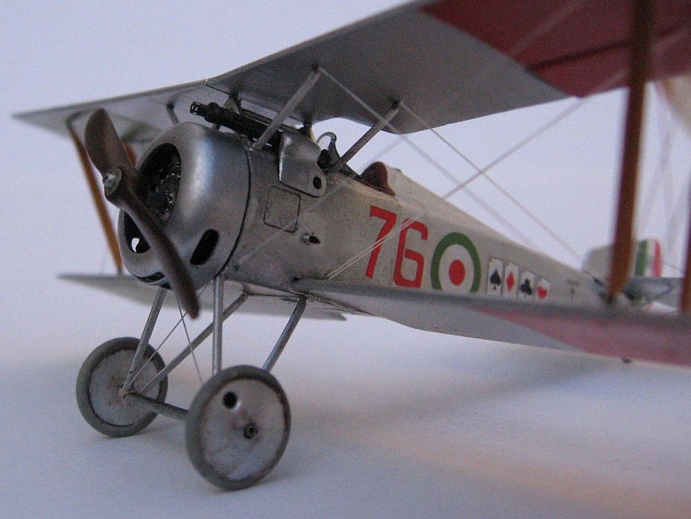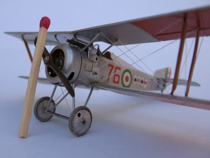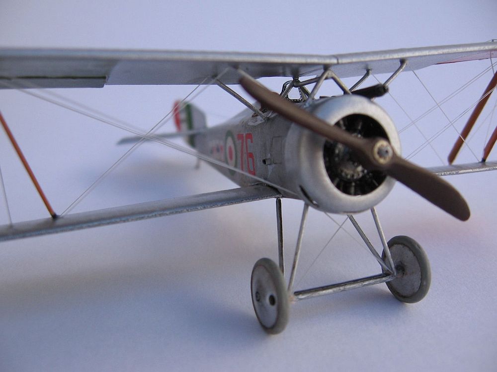
HR Model 1/72 Hanriot HD.1
By Diego Fernetti
The Hanriot HD.1 kit by HR Models captured the purposeful looks of this lightweight fighter. The First Look review promised an enjoyable build.
Even when it's a short-run kit, the style and layout reminds me of the best 1:72 kits from Roden, and I wouldn't be surprised if they shared the same designer. The model seems to be based on Ian Stair's drawings in the book "French Aircraft of the First World War ".
The kit has crisp moldings with thin attachment points to the sprue tree. Even when it has little, if any, flash around the mold parting lines, you should clean each piece thoughly to improve its fit. The soft light gray plastic is very easy to work but hard to see, so good lights on the workspace are mandatory!.
The Puzzling Fuselage
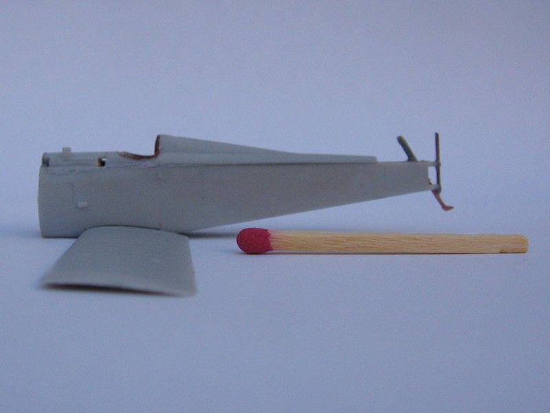
This is not your regular, run-of-the-mill, two-piece affair: the "body" of this airframe is made up of several parts that should fit together: two sides trapping a two-part circular flange on the firewall, cockpit coaming and rear turtledeck, and front decking. This seemingly odd puzzle is designed so the delicately molded surface detail along the spine and the centre line ahead of the cockpit won't be obliterated by sanding the seams after assembly. And those seams are minimal if you are careful cleaning and joining each part.
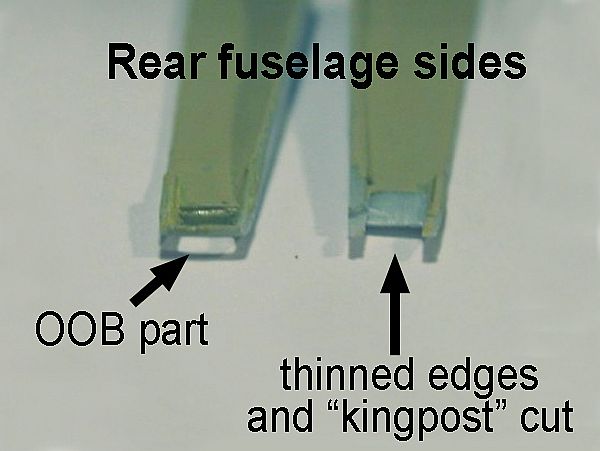
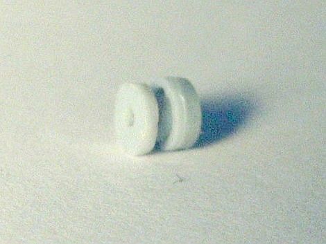
Both fuselage sides (Parts 10 and 11) have the correct cutout by the tail, but note that each one has a tail kingpost molded in it. You should cut off one of them, or else you'll get two parallel kingposts in the tail, which is one too much. Don't forget to sand a little along the upper edges of these parts, as they have a near invisible molding line that may interfere later with the proper fit of the separate turtledeck (part 23). The infamous Part 42 (drawn on the instruction sheet as a shallow cylindrical piece with a flange) should fit inside a central aperture in the firewall. In fact, part 42 doesn't look much like the drawing, being a thick little disc with a hole in the middle. At a later stage, this hole should fit tightly around the engine rear "axle" (part 34), as both these pieces form a sort of sheave, that inserted on the firewall allows the scale rotary engine to spin along with the propeller. I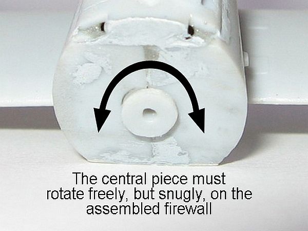 altered the assembly order, adjusting Part 42's to fit the axle of Part 34, making sure that the sheave moves freely in the firewall aperture, but not as loosely that the engine would droop off centre inside the cowl. Or you can skip all this entirely, and glue part 34 to the firewall, and have both rotary engine and propeller fixed permanently.
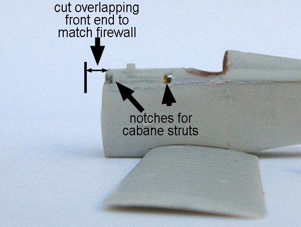
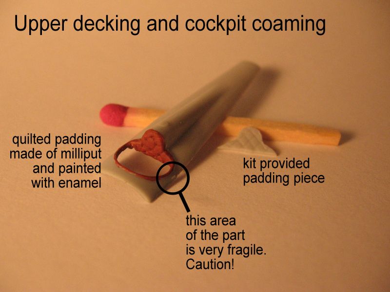
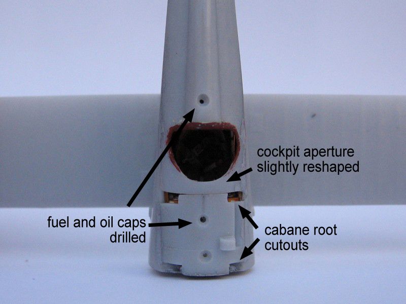
The front decking (one of three options in the kit), is a curved affair which includes a number a details –and most importantly the attachment points of the cabane struts-. Its rear edge should meet the front of the cockpit coaming and aft turtledeck. Unfortunately the front decking is molded more than 1mm too long! This throws off the geometry of the cabane struts (thus, the stagger of the wings), where the machine gun is attached and the placement of the cockpit along the fuselage length.
Don't despair yet! The solution is simple, but requires a bit of surgery: cut that pesky surplus length off the front of this piece. Then carefully notch each front corner with a sharp blade, where the front cabane strut roots will sit later. Remember: the struts sit directly over the firewall, so there's not difficult to place the notches correctly.
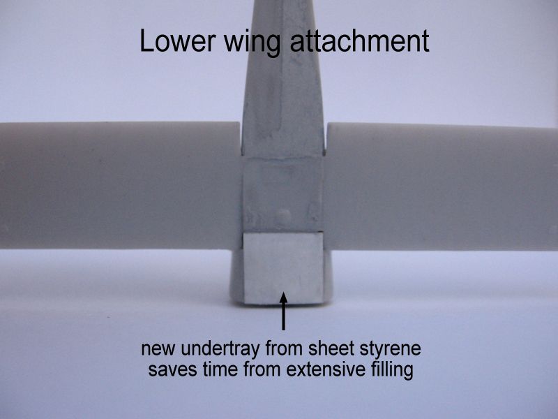
The lower wings (Part 3) are molded together with the central portion of the lower fuselage that slots into a cutout in the belly of the fuselage. More on this later!
Once assembled, the firewall lacks the typical exhaust channel (an angled surface behind and below the engine) found on most rotary-powered airplanes. Checking my references indicated that only some Hanriots had them, and thus I chose not to add it to the model.
A Busy Office
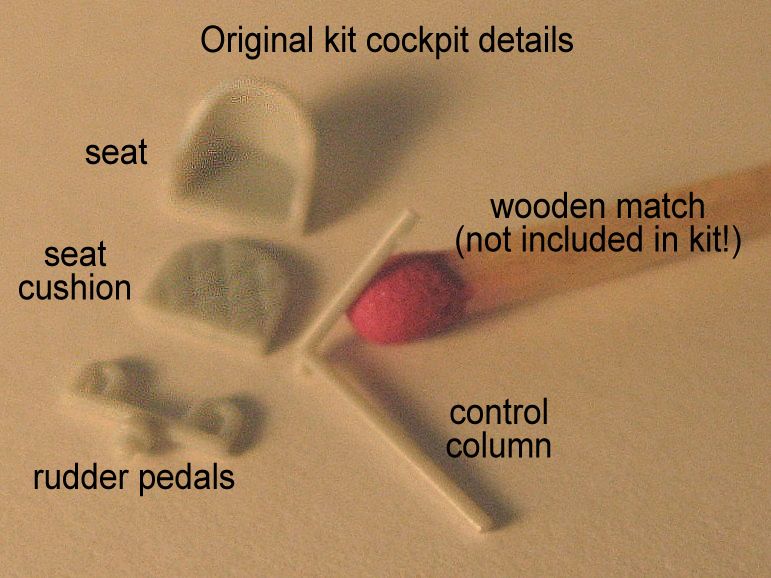
Given the relatively sparse cockpit of the kit, I chose to detail the interior with some scratchbuilt items -and complicating my life !-.
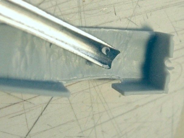
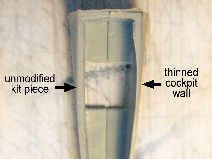
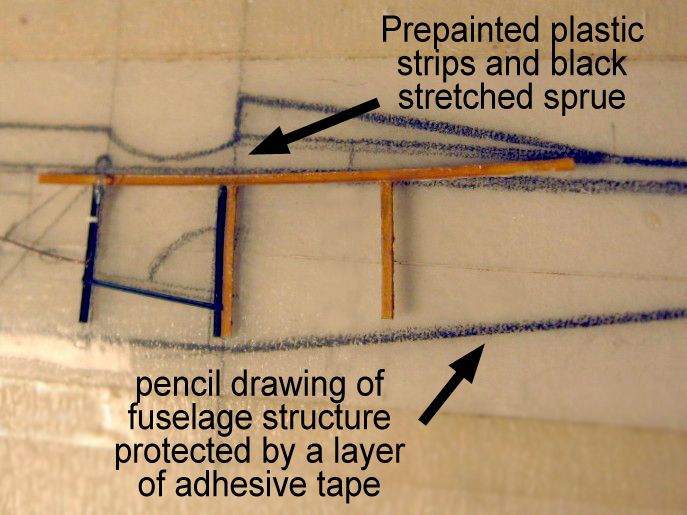
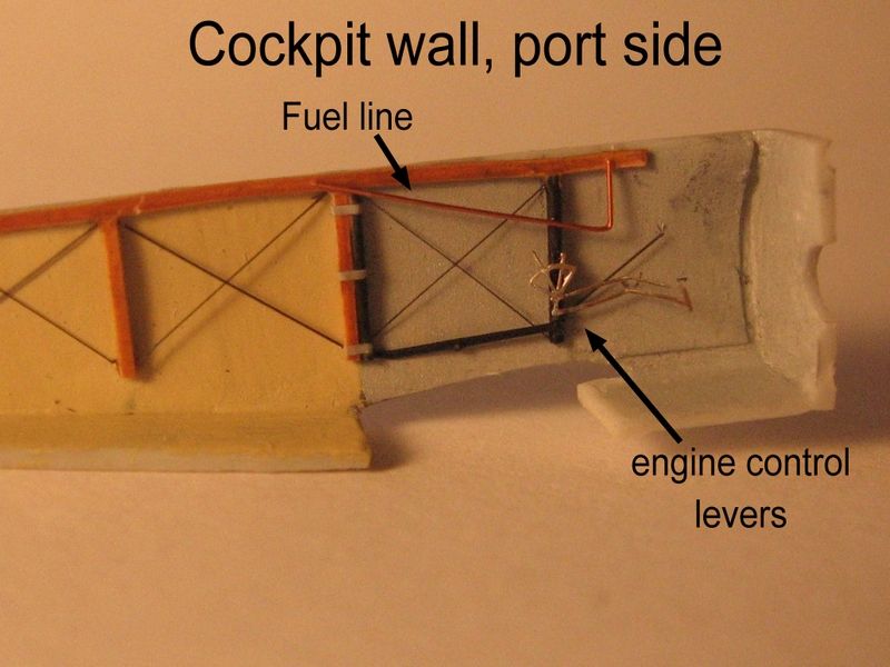
The process starts by thinning the fuselage walls to achieve a more scale appearance and having more room to add extra pieces. For this, I used a small gouge, taking small slivers of plastic on each cut. It's a slow process, since the tool may go through the wall if carelessly handled, and while fixing a hole is relatively easy, you may feel like an fool, something I'm rather used to, but that can itch if you're not practising everyday as I do. The uneven "wavy" gouged inner surface was smoothed with sandpaper. An easy way to know if you sanded enough material is to offer the part to a strong light source: the thinned area should look lighter than the surrounding plastic. If you sanded too much, you might see the light source directly, so depending on where you model, you should be careful and use sunglasses just in case.The cockpit structure is based both in references and measurements of the kit fuselage itself, as there are slight discrepancies to take into account if you want your details to fit accurately inside and out.
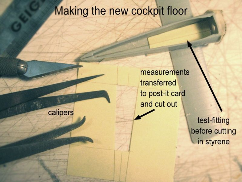
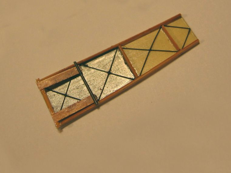
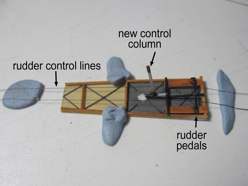
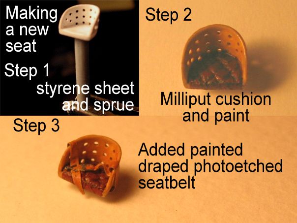
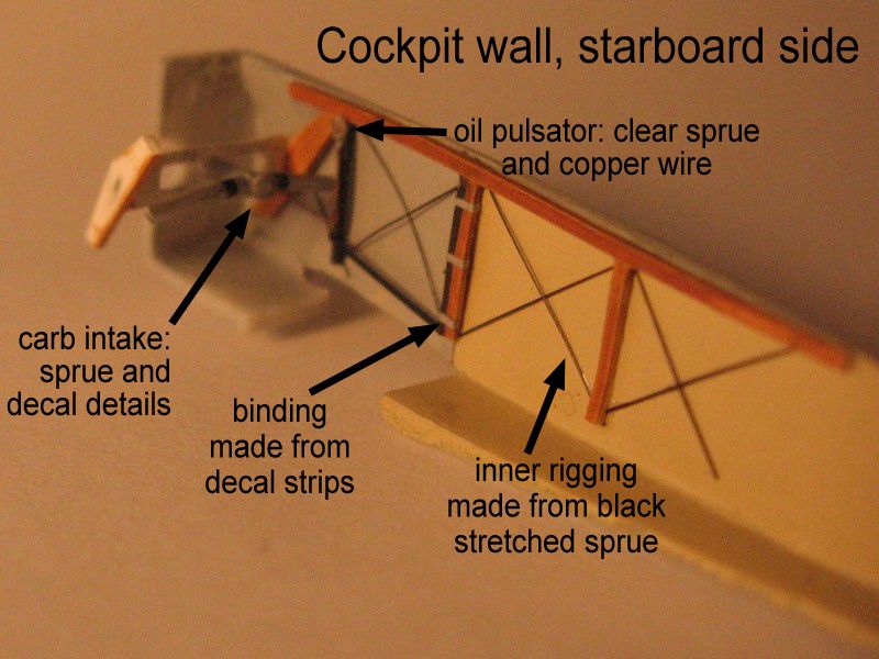
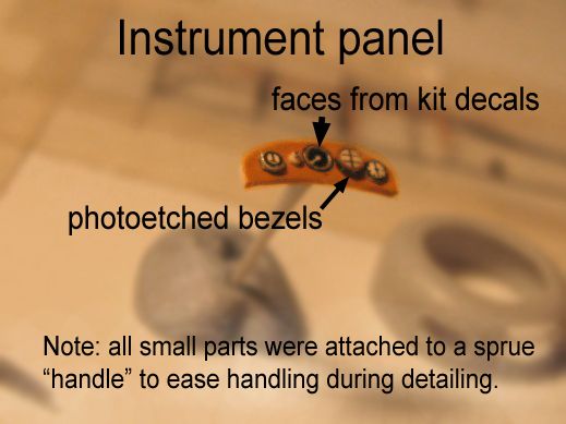
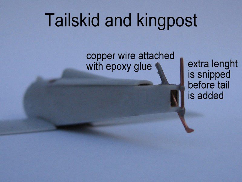
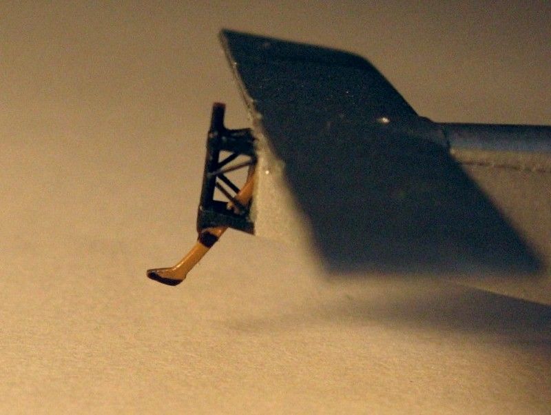
I made a paper pattern to cut a 5 thou styrene cockpit floor, to hide the interior central seam of a model fuselage. On this floor, I added the lower longerons and structural cross pieces, a rudder bar, heelboards, and cross and control wires. I also installed the control column, and a detailed seat with a seatbelt from Tom's Modelworks WW1 "French Interior" photo-etched detail set. Using the decals from the kit, I replaced the instrument panel original part (that doesn't fit anymore, once the fuselage was thinned) by a better shaped styrene replacement. I painted the panel as "wood" and then put each face separately, as the real thing had some instrument cases screwed on to the panel, and some installed behind it. This is impossible to make with just a decal slapped on a flat surface! I framed each instrument face with a photoetched bezel, fixed simply with a droplet of Future floor polish. Once dry, Future shrinks and keeps the bezel in place without any glue spooges showing up. For some instruments, I added more droplets of Future to get a domed glass effect. Behind the panel I added a squarish piece of styrene, representing the ammo box installed there and that was visible on the reference cockpit pictures. By this time you should be fully aware of how obsessive I am about the fuselage interior. So, to make the picture complete, I thinned a bit the exposed tail structural longerons and "fabric" edges, and discarded the flimsy plastic tailskid part for a sturdier one made from copper wire, filed to shape. This is important: the model will rest on this small point at the rear, and it's better to make sure that the tailskid (and undercarriage) are as strong as possible. I also replaced thefuselage kingpost with a short, straight length of copper wire, which made the rear of the assembly sturdier. Diagonal lengths of black sprue were the final touches for the tail area structure.It was time to paint the interior surfaces: aluminium grey for the side panels and clear doped linen for the aft fuselage, as you can see a good deal on inner surface on the assembled model by perusing inside by the cockpit hole. You don't want to see a bare plastic spot once you can't reach it!
I fixed the structures to each fuselage half using just Humbrol matt varnish, making sure that the uprights on each side won't interfere with the lower longerons of the new floor later. Then glued this floor (with seat, pedal, etc. on it) to one half, trying to align the structural elements to the wall details, and later on, I added the instrument panel and carb air intake, the other "crossing" elements inside the cockpit. Everything must be properly set and measured up before closing the fuselage, a milestone on the build process.Cabane Struts, and the other ones too
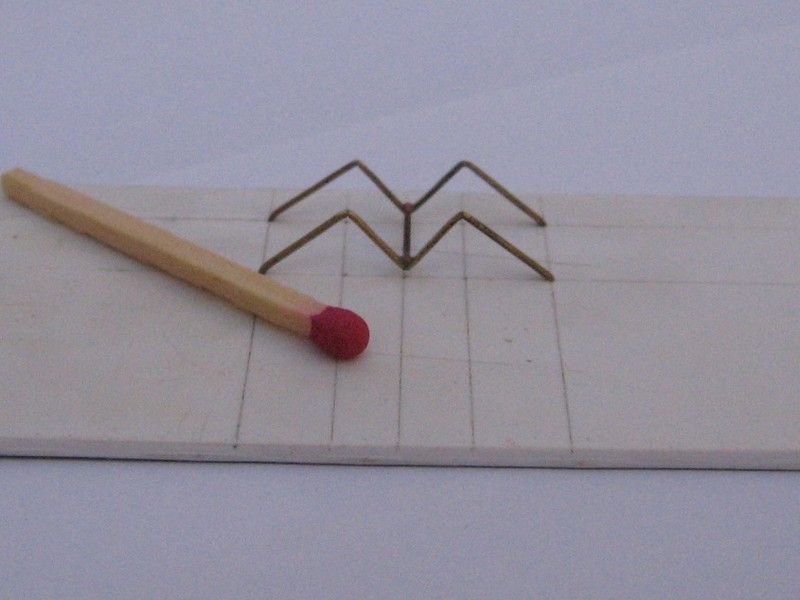
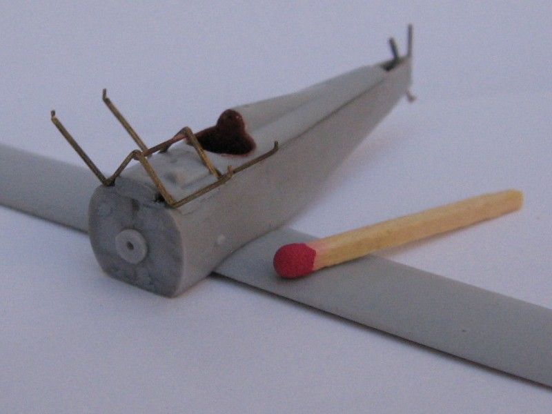
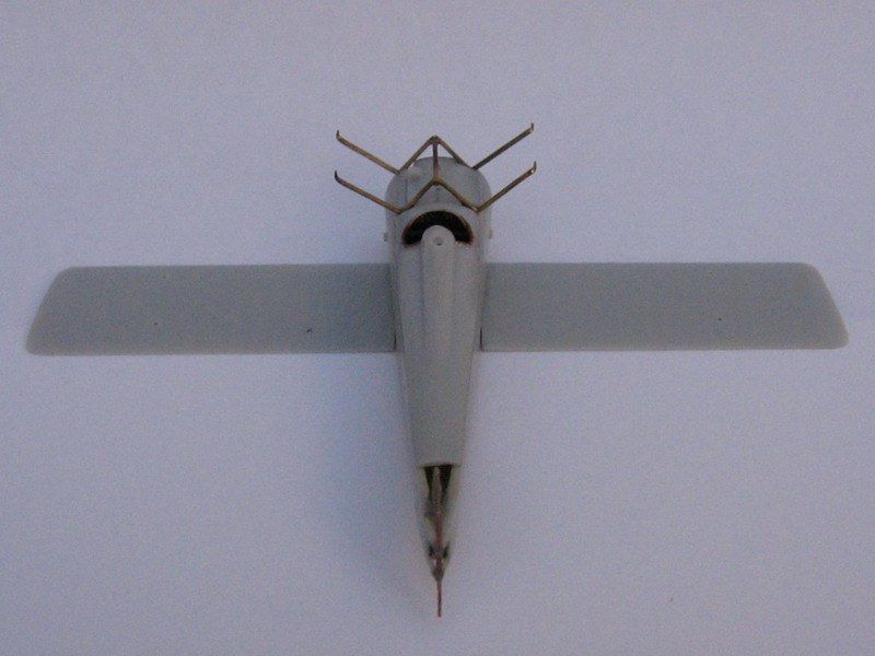
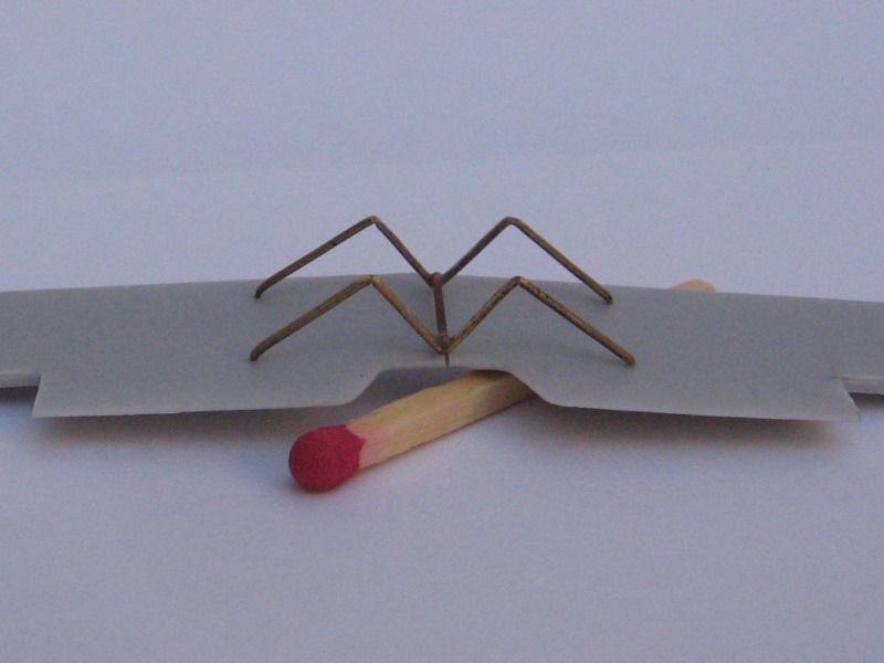
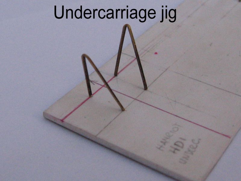
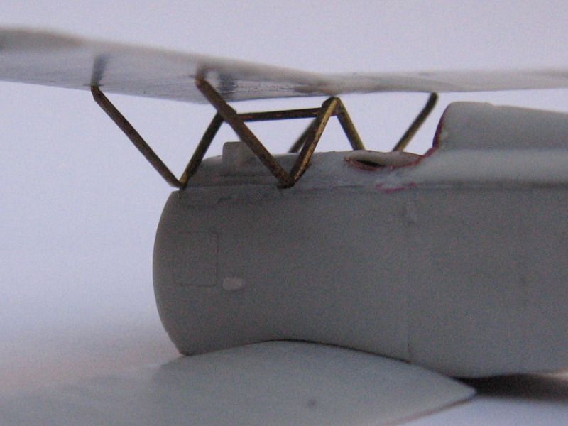
The Hanriot HD1 had an unique cabane strut arrangement. Imagine a double, streamlined steel W sitting across the front coaming. The kit includes weak and rather clumsy lengths of plastic to assemble the cabanes. However I thought this might endanger the bond between the upper wing and the fuselage, so I bit the proverbial bullet and made new cabane struts of "Strutz!" extruded brass lengths. It was easy, and to make sure I had them bent equally and accurately, I made a jig placing holes on a scrap of thick styrene sheet in the same spacing as the roots on the fuselage coaming, and the ends under the upper wings. The two Ws were joined with a cross piece along the central edge and epoxy glued to the fuselage, using the upper wings (part 12) as a help to place the struts correctly. The outer wing struts were spot on in true length according to my reference drawings. Remember that a 3-view drawing won't show the struts true length because they're slanted in side and front views, but determining it is a simple geometrical trick. I refined them a little sanding their trailing edges and shaping the end pins more sharply, so they would fit the holes drilled on the wings. When the upper wing was finally assembled, they just popped into place!Wings, Tail Surfaces
The lower wings (part 3) include the lower centre section of the fuselage, and it should fit a slot below it. On my model, fitting it took a while, as the wing slot on the fuselage was too narrow for the centre of the lower wings. Careful sanding of the fuselage slot edges, centre section of the wings and adjustment of the curved edges where the wings should meet the fuselage sides, eventually made all the parts click together. I thinned a bit the centre of the wings to make room for the new styrene floor of the cockpit. Finally, I deepened the strut location holes, and made new, shallow ones where the rigging was to be anchored later. Note that the aileron control line exits on the upper surfaceon the lower wing were absent on the kit, so it's easier to locate this and drill them when the model upper wing is still off. The upper wings had their control surfaces separated and edges cleaned up, its strut attachments deepened, and the central engraved line emphasized with an engraving tool. This should represent an actual gap between two separate wing panels, so it's adequate to make this noticeable at glance. This scored line goes around the leading edge, over the wing and round the trailing edge. It weakens the upper wings part, so it was done last before painting, to avoid an accidental damage before assembly. Do it carefully, though, to avoid cutting the wing in two! The tail surfaces are thin, with near-perfect surface details. A thick coat of paint may obliterate the contours of the structure molded on the surface! I drilled a tiny hole where the rudder fin will be attached to the stabilizer, cut the control surfaces and cleaned up all its edges. I added control horns to the rudder (you may choose a few shape options here as well) by cutting a thin slot in it and adding a piece of thin, black styrene across its edge. I left the styrene larger than needed so as to have a handle to paint (a white basecoat) and decal the rudder. When all was finished I cut the final shape of the control horns with a new #11 blade.That Cheeky Hotchkiss
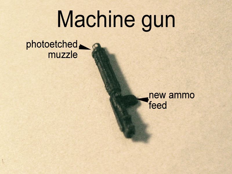
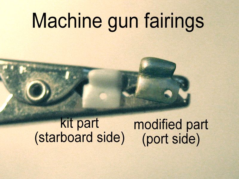
Hanriot scouts had a few different gun arrangements. Most had a single synchronized Hotchkiss machine gun mounted behind the propeller. Some had the gun mounted on the upper port longeron (where ammo jams were hard to fix), some had it mounted centrally (where surely they obscured the entire pilot's front view). But some entrepreneurial spirits had even two machine guns mounted at each side. The kit provides the three options with different front decking parts, that include fuel and oil caps placed accordingly, a recess where the actual gun sits and small ammo box feed dimples on the adequate places. My references stated that I should choose the port mounted option. But remember I told you before that this front coaming should be shortened 1mm at the front to fit the fuselage length? Well, that threw off the ammo feed off, and it had to be sacrificed in order to place the gun correctly over the angle of the cabane struts! To replace it, I cut a small slice of sprue and glued it to the machine gun (part 22, gentlemen, and it comes twice on the tree). The gun itself is surprisingly coarse, given the high quality and subtleness of the rest of the kit. But once cleaned up, painted and accented with a rub of a graphite pencil lead, it's a decent representation. I only added a photoetched muzzle to it, as to improve the only area where it can be seen clearly on the assembled model. Some Hanriots had also a unique streamlining cover over the ammo chute, a sort of "cheek" which covered most of the gun rear. I took the chance to add this, but the kit part 37 had a slightly different shape and its hole was placed differently than on my photo documentation.So, as you can imagine, I spent an enjoyable afternoon changing the shape of this 3mm plastic chip, which ended glued to the side of the fuselage, as if the machine gun would have a large artificial ear.
Cowl, Engine and Propeller
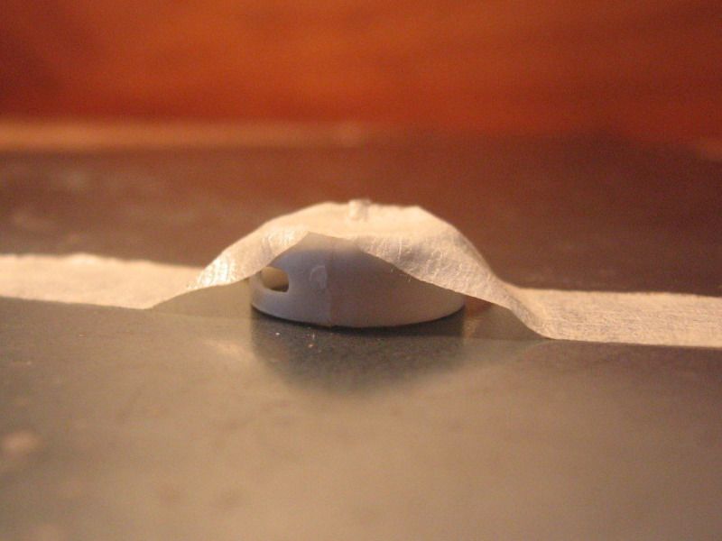
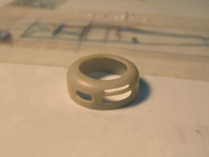
The cowl is formed by two pieces (parts 1 and 7) that glued together form a ring of the same diameter than the front of the fuselage. You may sand the mating edges flat to get a better gluing surface, but sanding too much may result on a cowl that isn't perfectly round.To avoid excess sanding, I took a compass and drew a circle on a piece of card, adding a line across its centre. Checking as often as possible, this line helped me to ensure that each half has the right shape, and both joint along the diameter, keeping a regular, round outside shape. Once ready, I joined the two halves together with as little glue as
Personally, I would have liked the cowl to be molded in one piece (perhaps there are some molding limitations that dictated otherwise), but I have to acknowledge that if you prepare the parts mindfully, both halves fit and the seams along the cowl sides are minimal and easily filled up with a smear of putty.
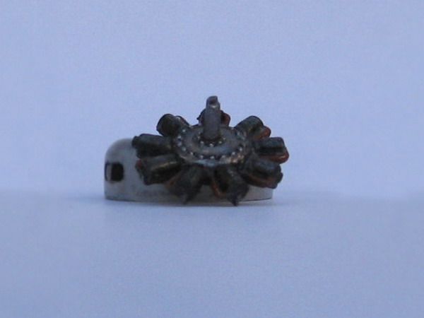
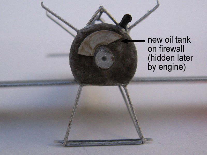
The engine on the kit (part 32, and you get an extra, part 26 "Clerget" engine which can be used on the Hanriot HD2) is very nice and detailed "as it comes". Unfortunately, not much of it can be seen once it's enclosed inside the cowl and behind the propeller. I used the kit part painted in several contrasting shades of silver, aluminium, gunmetal, black and copper paints, plus a careful wash of thinned India ink, which imparts it an oily finish overall. The rear has a round depression that should fit the round "axle" piece (remember that sheave on the firewall?). Well, it doesn't fit much... Besides, the engine sits too deeply inside the cowl, making the propeller too close to the cowl lip. I saved all the trouble by inserting a small piece of styrene sheet inside the engine rear leaving it level, and gluing this to the sheave face. The engine then sits clear from the firewall and still inside the cowl. A finishing touch was to add to the firewall a 10 thou piece of styrene shaped as the oil tank. A waste of time, since it became impossible to see once the engine, cowl and propeller were assembled later!The propeller –"airscrew", being pedantic- is correctly shaped like those in most references. However, a common problem with propellers in injection molded kits is apparent: there's a mold parting line along all surfaces, the tips and trailing edges aren't sharp enough and the hub should be a bit more substantial and have sharper surface details.
I smeared some putty around the hub sides, and when dry, I sanded and filed this to give the centre of the propeller a sharper and more cylindrical shape. Besides, I scraped and sanded the propeller tips and trailing edges to razor sharpness. The hub plate was accidentally damaged while doing this –glad I'm not a surgeon!- so the front and rear surfaces were sanded flat and a replacement photoetched plate was fixed to the mahogany painted prop body. I also added a back plate from a circle of styrene painted silver, since this feature was relatively easy to spot if the model is seen from the sides. Over the hub plate, I added a tiny segment of plastic tube, representing the hollow end of the engine axle, a common feature of the Hanriots. Styles of hub plates and retaining bolts can vary, so it's always useful to check with pictures of the real thing when available.Again, the propeller is correct as it comes on the sprues, but the purist/obsessive may like to spend a few minutes making a better representation of the real thing for a piece that's so "in the face" of the model.
Landing Gear
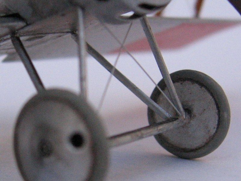
The kit undercarriage legs are a little clumsy. The cross section of the parts is noticeably un-streamlined. If the instructions were followed to the letter, the strut ends should be butt joined to the fuselage, which would made the model extremely prone to self-disassembly.
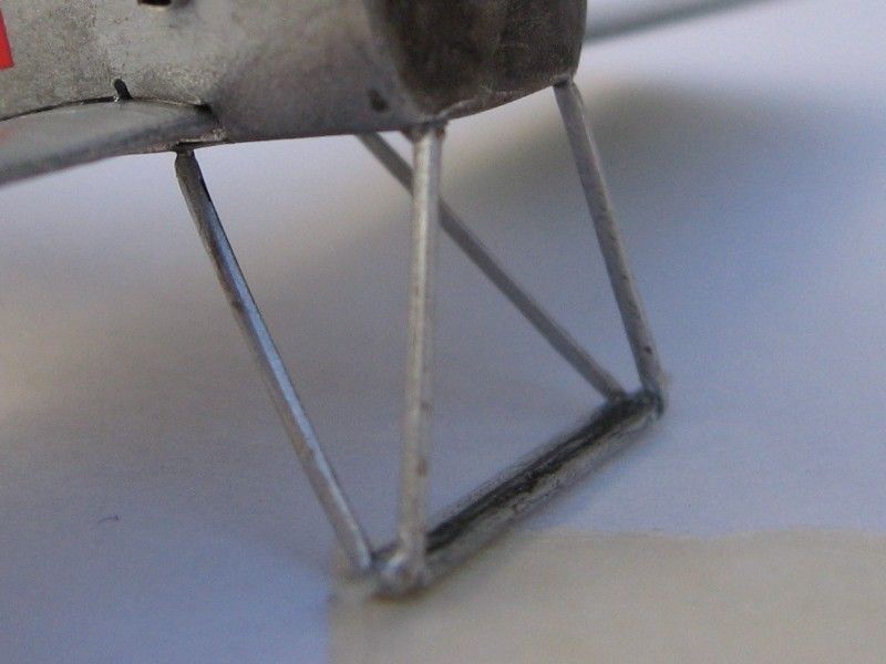
I attempted to refine it by sanding and scraping with a hobby knife, but ended up breaking it. I put too much strains on parts that were small and delicate from the start. Gluing again the broken leg won't do, so I made a new pair of vees from extruded brass lengths. That gave me a sturdier undercarriage unit and taught me a lesson when not to mess with soft plastic for small, thin features that also serve a structural purpose.
I drilled 4 holes for the undercarriage in the fuselage belly.
The wheel axle is molded straight and along with two spreader bars around it. In the real airplane, however, the axle was "split" on a central flexing point. After the sobering experience of the legs, I used the axle straight from the box, as it had the correct width and was strong enough to endure frequent fiddling during the assembly process.
I made a jig to put the fragile undercarriage structure together without handling the rest of the model. I glued the strut pins in them with white glue, but used epoxy glue to fix the axle to the vee apex, always checking for the correct placement along each guide line marked on the base sheet. The result is having the undercarriage (less wheels) assembled upside down on the base. Once all joints were dry, the assembly was freed from the styrene base. Then, it's just a matter of gluing it again to the model fuselage, and touching up the leg roots with a dab of paint to hide the joint. Careful, as this structure is weak until you add rigging to it, since this makes it stronger as it was in the real thing.
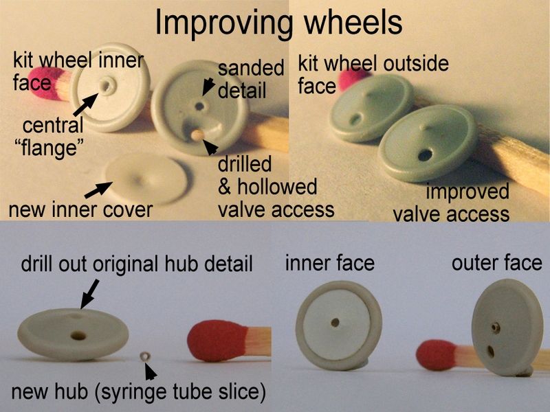
I also spiffed up the wheels, that were molded with a small pimple for the axle end and dished canvas covers over the outside face (the covers were used to keep the spokes free from dirt or mud besides being a simple streamlining device). The hole for the pneumatic valve is just a shallow depressed circle. The inner face of the wheel was a flat surface with a round "flange" instead of the prototypical shallow cone.
I shaved off the central flange and gouged the inner face behind the cover valve hole getting near-scale edges for it. A new inner cover surface from 0.05" styrene was cut and dished –slightly!- by pressing a drill bit butt on the centre, over a magazine (don't do this on your valuable reference material as this leaves dimples on it! Don't ask me how I know). Paint the interior of the inner wheel cover matt light grey, then glue it to the outer section of the wheels. I also drilled the centre of the outer wheel cover, and added a small section of bright syringe tube as the axle end. Without them, the wheels still resembled a small plastic nipple! The final step is to glue the pre-painted wheels to each axle end, and bind a few turns of sewing thread with white glue to represent the bungee cords.
Hanriot's Not-Too-Many-Colored Coat
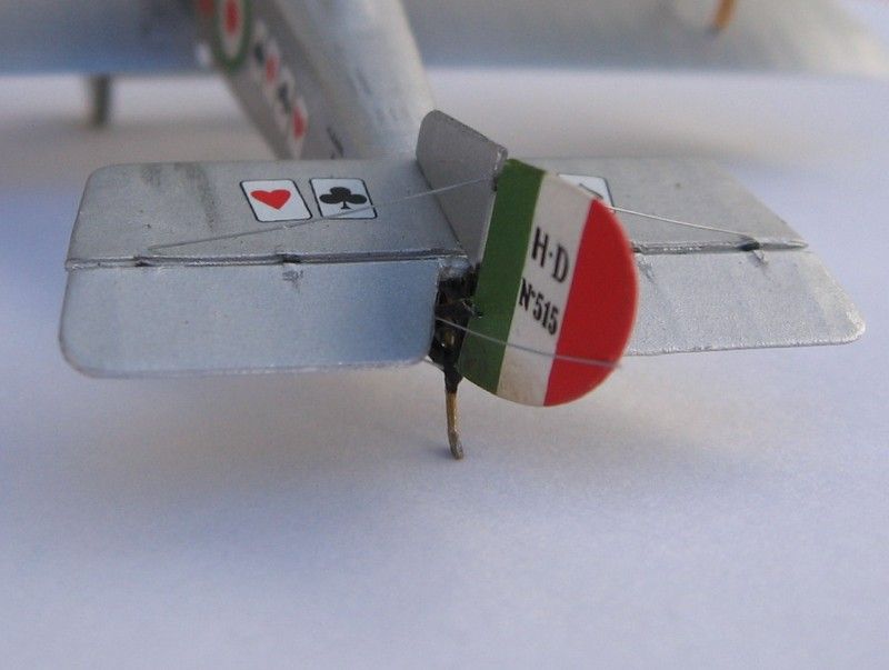
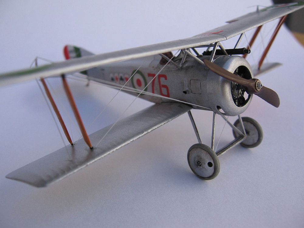
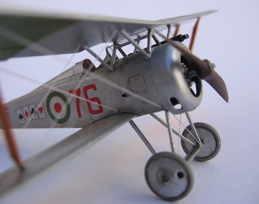
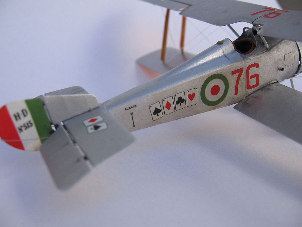
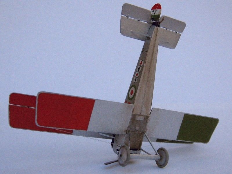
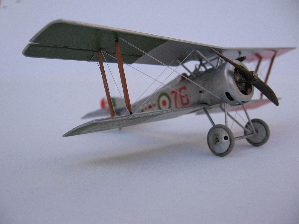
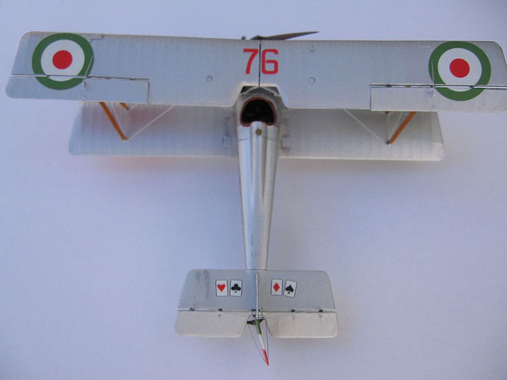
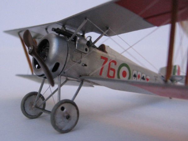
I chose for my model the paint scheme of Tenente Flavio T. Baracchini, (No.515), decorated with a poker of aces at each side of the fuselage and over the tail, one of the various decal options offered with the kit, and the subject of the box art painting. Instructions state a clear doped linen colour overall, however, this photo shows the surface shine of a brightly aluminium painted machine, which was typical of French imported machines. Thus I painted the model entirely with Humbrol 11 enamel. Since the front fuselage panels and cowl were just bare aluminium sheet on the real airplanes, I used a thinned mix of water and "Boltgun Metal" Citadel acrylic over these panels, that gave a slightly darker hue to the front of the bus. According to marking practices of the time, all wing undersides were painted with areas of "Flag Red" (port) and "Flag Green" (starboard). The underside of the wings had a small "return" of the silver colour of the upper surfaces, and doing this neatly had me scratching my head for a good while. I have a silver Sharpie marker, which matched the Humbrol 11 paint spot on. I ran the side of the tip around the edges of each wing and voilá: silver edges! I left it to dry a few days and sealed the colours with Future, which gave an uniform sheen to the surface.
The decal colours are perhaps a bit too vibrant for a scale model, so I toned them down slightly with a coat of matt acrylic varnish, and later a very thinned wash of sepia watercolour, that served as a more or less subtle weathering. I also brushed more heavily the sepia watercolour along the underside of the fuselage and a little under the lower wingroot area, the places where the cooked up castor oil of the rotary engine might catch dirt and it's less likely to be cleaned up by crews.
Rigging and Sundry Details
As usual, I use stretched sprue for rigging. This model challenged me because it has doubled flying wires, which must be parallel from each other but very close. I started out by putting the flying wires even before re-attaching the upper wing ailerons. This way, the rigging attachment points near the strut ends are easily reached and with a bit of trial and error, I added each wire to the right spot, using small amounts of white glue to fix them. If one of the lengths ended up a bit slack, I carefully exposed that "wire" to a small source of heat (an incense stick, for instance) and it usually tightens a little. Of course, if you use too much heat, the wire melts and curls into itself. More heat, and the whole model can catch fire. So forget about using bonfires for this delicate operation.
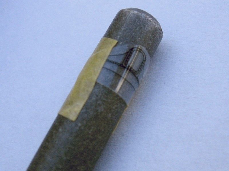
Speaking of heating things up, the kit offers three options of differently shaped windshield, printed in film. Anything you choose, must be curved in a way that fits the front of the cockpit. I taped the piece of film to a suitable round object (in my case, the aluminium handle of a modelling knife) and put that into a cup of boiling water. A few seconds later I put the handle with the film attached under a tap with running cold water, which "freezed" the film in a curved surface. Later on, using a new knife blade, I cut the outlines of the windshield and using "Mithril Silver" Citadel Paint and a fine brush, painted up the back (concave) surface of the "frame" of the windshield, keeping the neat printed outlines visibles on the outside surface. I had to reshape the lower edge of the windshield to adapt it to the decking curve, and later on I fixed that to the rest of the model using white glue, which also sealed any possible gaps between the parts.
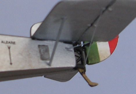
I cut tiny triangles of thin styrene sheet, painted them silver and added a small angled length of stretched sprue in one of its angles. I fixed the base of the triangle and the two ends of the sprue as the aileron control horns. Under the ailerons, a segment of sprue connects them to the lower wings.
The fuselage sides have two small pips that represent the intake pipes for the engine carburettor (these are not exhaust pipes!!!). As they were molded solid, I erased them and replaced by slices of aluminium tube, slightly crimped to have a teardrop shape. I fixed them to the sides with a drop of matt varnish.
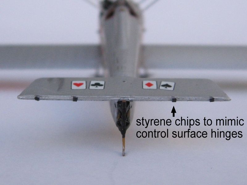
On early aircraft, ailerons, elevators and rudders were hinged to other fixed surfaces leaving a slight gap, a sort of see-through effect absent in more aerodynamically advanced aircraft. To achieve this, I glued the control surfaces to the wings and tail using small chips of black, thin styrene sheet between the pieces.
The last step was rigging the tail and adding struts under the stabilizer.
Then, I just sat there, staring at the finished model.
It was a great feeling.
Where To Know More
The references on this airplane are plenty and it's easy to find many useful detail pictures.
Bibliography
- Hanriot H.D.1, J.M. Bruce, Windsock Datafile No. 12
- Hanriot H.D.1/H.D. 2, Gregory Alegi, Windsock Datafile No. 92
- The Hanriot HD1, J.M. Bruce, Profile Publications No. 109
- Italian Hanriot colours, Article by Alberto Casirati & Bob Pearson, Windsock International, Vol. 18 No.6
- French Aircraft of the First World War, Arthur Zoltan & James Davilla, Flying Machine Press
On The Web
Many results can be found, but here are some that I considered to be of most interest during the building stages:
- World War I modelling pages
- Marek Mincberg Pages
- Flickr search result "Hanriot"
- Alberto Casirati's Hanriot HD.1 from Internet Modeler, April 2001
- Hanriot HD.1 build by PrzemoL on Modelarstwo Redukcyjne (in Polish)
Acknowledgements
A long, protracted build isn't possible without the help and encouragement of friends. I no particular order, I'm indebted to Paul Thompson, Shane Weier, Neil Crawford, Fraser May, Pedro Soares, Michael Kendix, Dave Hooper and Matt Bittner (who seems to be fate's agent for me to build a Hanriot). Thanks to HR Model for the review kit.

