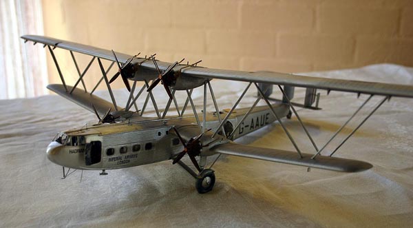
Building the 1/72 Contrail HP 42
By Graeme Carter
Building the 1/72 Contrail Handley-Page HP42/45
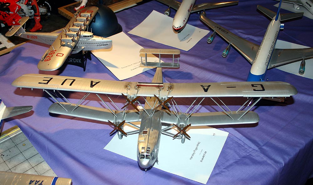 This great example of 1930's British Empire luxury air transport has long been on my wish list. Certainly an ugly duckling compared with the fabulous DH91 Albatross (see my build in SAM October 2000), this giant semi-sesqui-plane still captures the imagination with its huge corrugated fuselage, gull-like lower wings and 130-foot upper wing. The use of Warren girder inter-plane construction meant that no rigging wires were required except for the outer struts and the tailplane. Four Bristol Jupiters drove the beast at 116 mph (186kph) flat out or a sedate cruise of 94 mph (150kph) which, combined with a range of 300 miles (480 km), allowed for a gentlemanly four-course meal to be served between London and Paris. Unlike earlier airliners, both crew and passengers had cabins inside the fuselage and had wonderful views ahead and below from their large windows.
Only eight were built for Imperial Airways, four as mail/passenger transports for European or Western runs and were designated HP45 and called the 'Heracles' class; another four were designated HP42 and were set up for the Eastern routes into Africa and India under the class name 'Hannibal'.
The prototype ('Hannibal') was ordered in 1929 and there was no production line in the strict sense, each plane being individually constructed and, while the fuselage interiors were the height of luxury, the exterior was bolted, rivetted and screwed together to produce a fairly utilitarian finish. Study of any close-up photos reveal gaps between panels and rows of rivets that surely worked against aerodynamic principles. Flying surfaces and rear fuselage were fabric covered.
 The HP45 carried a crew of three and up to 38 passengers with mail/baggage up to 250 cu ft ( 7.1 cu m), while the lower rated, but longer-ranged HP42 had four crew, only 24 passengers but twice as much mail for the far-flung reaches of the British Empire. The eight planes logged up over 12000 hours in the air and no passenger was lost in accidents - the airliners were the first to log over one million miles (1.6 million km) in service, eventually amassing around two and a half million miles, and seven survived into the Second World War, three of them being converted into RAF service as troopers and officer transport with 271 Squadron. They were prone to being blown over in storms (can't imagine why!!) and four were eventually lost this way.
 I had long lusted after this beast and, having seen the lovely models in the iconic Croydon Terminal museum (base of the HP45s during their European service) in 2006 and, when a modelling mate produced an intact but somewhat battered box and offered it to me on the proviso that I build it as he was not going to get around to it himself (profuse thanks Jim), I started on it immediately.
The Contrail kit was released in 1980 - that's 29 years ago folks! - and represented the height of Gordon Sutcliffe's skills as a modeller and vac-form kit designer. The box contains everything you need - there is an interior, enough seats for the HP45, heaps of Sutcliffe Struts (more about later), many sheets of neatly formed parts, injected wheels, a set of fairly yucky white-metal engines and propellers, and a decal sheet covering all eight civil aircraft and the three war-time impressments, as well as plans and a set of interior and exterior photographs (a bit like a vac-form Italeri kit!).
The plans are a problem as the kit ones and the ones in Model Aircraft Monthly do not entirely agree and the kit parts differ slightly from both! Photos indicate further divergences.
References
The first step, as always, and delving into my collection I came up with a mass of photos and artices in Aeroplane Monthly; Scale Aircraft Modelling; the Aircraft Resource Center website; Aircraft Illustrated; Aircraft Modelworld; Scale Models International; Air International; Illustrated Encyclopaedia of Aircraft; and Model Aircraft Monthly, Paul Ellis - British Commercial Aircraft, 60 Years in Pictures - Jane's, 1980, ISBN 0 7106 0010 0, John Stroud - Airliners of the 1930's - Phoebus Publishing , 1980. John Stroud - The Imperial Airways Fleet -Tempus books, 2005 ISBN 0 7524 2997 3, Mike Hooks - Croydon Airport, The Peaceful Years -Tempus books, 2002, ISBN 0 7524 2758X.
Contemplating this lot drove me to decide to build HADRIAN, which is an HP42 with fewer seats and a larger mail store room and I decided to build a detailed interior.
The Fuselage
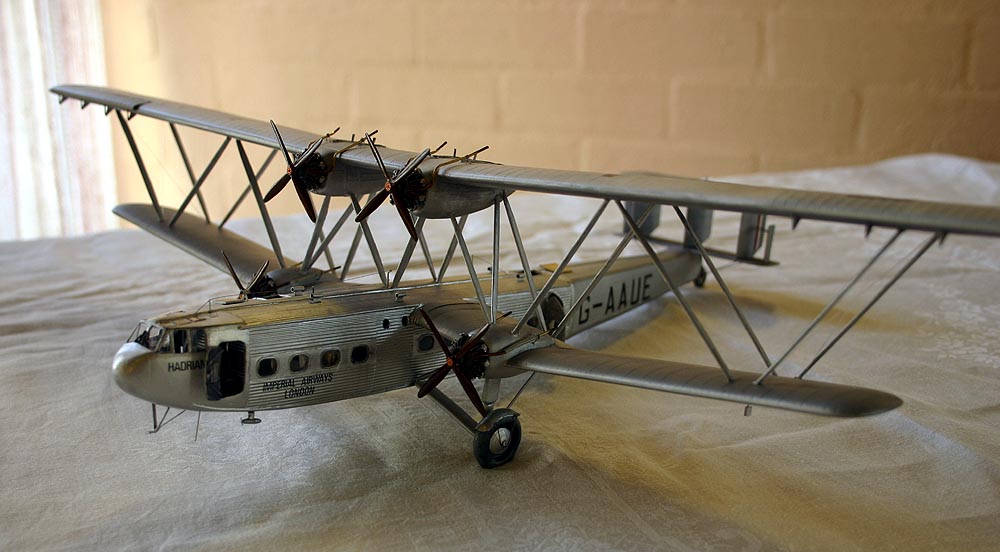 I cut out all of the windows while the halves were still on their backing sheet - this gives you much better rigidity when drilling and cutting, making sure that the cabin windows did not go into the beading around them and that the cockpit openings are as fine and square as possible. I also cut open the crew and passenger doors on the port side at this stage.
Fuselage halves were then separated from the backing sheet using a sharp blade and sanded to mating surfaces, test fitting frequently until they matched. Strips of scrap plastic were glued all around one half to act as locating tabs.
I collected as many pictures and drawings of the interior as I could before starting. Curiously there are hardly any photos of the cockpit so I used a cutaway, a couple of photos, the info on the instruction sheet and some imagination. Interestingly a web search found that a flight sim is available and I downloaded their cockpit but it was scarcely more useful than the drawings. All cockpit details were from scraps of plasticard and bits from the spares box. Note that one photo has full steering wheels and another has a cut-out in the upper section. The radio 'compartment' was furnished with a folding seat (past which the crew had to squeeze as the radio operator sat in the entrance doorway) and a radio, shelf and headphones - all visible through the open door.
I replicated the corrugated interior of the crew and service areas myself because the vacform pieces just would not fit the fuselage so I purchased a sheet of 'real' corrugated iron in railway scale and proceeded to make bulkheads and walls in 15thou plasticard and then glued the corrugated sheet onto one or both sides as needed. I also used real wood panelling and found some lovely 1mm dark cedar veneer from which to cut all the cabin walls and bulkheads. They were attached to the fuselage walls, covering the windows and then I carefully drilled through the veneer and sanded the interior shapes where each window was. The red carpetted floors in passenger cabins were Humbrol 20 with a coat of matt. Ceilings were Sycamore veneer for which I used Airfix M14 with a satin coat, and I cut the luggage racks from fine mesh and painted them brass before attaching them above the windows. All of the interior corrugated surfaces were left in 'natural metal' and look great through the windows. A couple of tables were made and located between pairs of seats with tissue paper tablecloths, also used to make the curtains which were positioned in a variety of ways at the windows, being careful not to put curtains in the mail compartments - these were left bare as can be clearly seen in all photos and is a quick way of identifying the Eastern and Western models. During this stage of construction I must have trial fitted and jiggled and sanded and fitted the parts together a hundred times.
The kit seat parts are terrible and I scratch-built a dozen based on photos and drawings. Each consisted of eleven separate parts and Milliput shoulder cushions which were glued together and painted a yellowish-cream, then using the veneer again, I added the rear panel and sides and clear glossed the timber before carefully drawing a Jacobean pattern of green rose branches and red flowers using very sharp colour pencils. A lead pencil was used to highlight the cushions and then they were all glued into their relevant places in the two cabins.
The fuselage halves were now joined and after a couple of days to dry out I then filled the joint-line - mercifully only a little job - and sanded it smooth adding two fine strips of 5thou card to the tail section to represent the upper and lower stringers there and to cover up the joint line. Two roof hatches were cut out to allow internal inspection of my interior work.
Wings and Tail
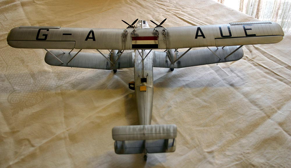 The lower wings have a gull-shape and come as quite complicated mouldings, including the lower nacelles. This shape was maintained using sanding blocks, a scalpel blade drawn sideways across the the edge, and lots of test fitting. A sharp trailing edge was quite easy to produce and then the parts were glued together. A block of pine was sanded to an aerofoil section to be glued inside the open end of the inner end of each wing and these would later be drilled to take the brass rods that would act as spars through the fuselage.
The whopping great upper wing is one length and along with the tail planes need fine trailing edges, and I used some heavy duty electrical assistance here. I made a set of tape 'handles' for the outside surface of each part and, with fairly coarse aluminium oxide cutting paper attached, mounted my half-sheet orbital sander upside-down in a vise with the dust extractor fitted. Apart from almost vibrating my fingers and wrists from their sockets, this set-up worked brilliantly and, after a brief hand cut with wet'n'dry, allowed very sharp trailing edges to be produced on all surfaces. The mainplane has the leading edge moulded onto the upper surface which calls for some care in sanding but produces a pretty good finish provided you use a strong supporting ledge along the lower leading edge and you make sure the mating surface on the lower wing is absolutely straight and true.
The tail empennage was then glued together, making sure that all fins were identical and that their upper and lower edges matched the surfaces of the horizontal planes. There should be no gaps or filling of these joints as the real surfaces just butted together. The whole structure should be square and true. I had made up the rudder balance tabs from 20thou strip with a 5thou slot at the leading edge but did not add them at this stage.
The ledge in the fuselage for the tailplane was deepened at the front (the instructions admit that Contrail had 'got it wrong') and the tailplane was then attached to the fuselage, making sure everything was square in all three planes.
Very careful measuring and attention to photos allowed me to mark the lower wing positions on the fuselage sides and I drilled two holes about 2mm wide right through the fuselage and the internal bulkheads, which were fortunately firmly attached, and two lengths of plastic tube to act as spars were inserted and glued. It is important to get the upper wing surface flush with the cabin roof top and the rear trailing edge at the right angle of attack. Fortunately Contrail give you extra length in this section of wing so that you can cut and shape the wing ends to fit the fuselage. I was going to replace the corrugated section on the top wing so sanded that off.
Holes were drilled for each strut-end on the wings and nacelles - these are marked with dimples on the upper surfaces. The wing ends were then carefully drilled through the wooden formers to match the tube positions and lengths of 1mm brass rod bent to the correct angle were epoxied into the wings, their fuselage lengths being half the width of the fuselage. I made a thick card jig to maintain the correct wing-fuselage angle and slid the wings into the spar tubes to check everything one last time. Easing the wings out slightly I applied epoxy glue, pushed them in, sat them in the jig, taped all components together and let it all set.
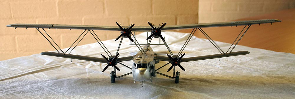 It is extraordinary that a flush wing section was butted onto a corrugated fuselage, but that is what they did! A small metal fillet filled the leading edge and a corrugated sheet was rivetted over the top of the wing and fuselage to cover up the joint, leaving quite a gap at the rear - just look at the photos. After making a paper template to test fit, I used more of my railway corrugated sheet to make the wing fillets and their thin metal surfaces enabled me to bend and knead them into position just like the real ones.
Undercarriage parts were prepared and another jig constructed as well a spar hole through the fuselage to spread the weight taken by a straightened paper-clip glued inside the main strut, with the end bent to match the angle when on the ground. I used the widest Contrail struts from the kit to make the vertical and sloping struts to meet up with the lower nacelles, then added the narrower ones up to the wings. It was all left for a few days to fully harden. It was starting to look like an aeroplane now - a gull-winged monoplane anyway.
The gigantic upper wing was sanded as smooth as I could and the ribs and leading edge riblets rescribed before I cut out the ailerons and used a sharp blade to scrape out the front spaces where the leading edge slots fitted in. . It was here that I noticed something that all photos but none of the drawings or the kit show - the wing-tip outboard of the ailerons has a distinctive 'hook' in it and I added some plasticard and filed and sanded this to shape. The aileron hinges and the L/E slot hinges were made from shaped bits of scrap. The slots themselves are separate mouldings and these were mounted in the half out position on the top wing as shown in most photos of aircraft on the ground. Ailerons were sanded to a rounded leading edge shape and glued into position. Finally I constructed four sets of inlets caps and overflow pipes for the upper wing fuel tanks,noting that these are handed.
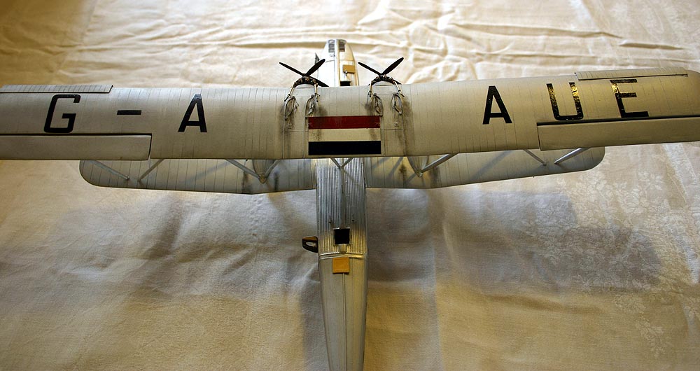
The wings and airframe was now painted. The forward fuselage is polished duralium and I used Humbrol 'polished aluminium' Metalcote 27002 which gives a lovely hard finish. The rest of the airframe is aluminium painted fabric and shows up as distinctly duller than the metal surfaces and I used Humbrol 'aluminium' Metalcote 27001. It took two whole tins of the latter to adequately cover the beast!! I had decided to model one of the three Eastern models that survived into WWII, returned to England in April 1940 and were later camouflaged when they joined 271 Squadron in June. In this short period these aircraft carried distinctive red/white/ blue stripes below the upper wing-tips, over the upper wing mid-section and on the outer vertical tail feathers on their silver finish. I presume that they were getting a little tatty by then so the fabric areas were allowed to get a little blotchy, so I polished the aluminium with a fine cloth more in some areas than others. I chose HADRIAN as my subject as it spent two or three months fluttering around England before being camouflaged as AS982 and later being destroyed in a gale in December 1940. The finish was deliberately left a bit patchy as I reasoned that this aircraft would not be as well looked after as it had been for its commercial service in the Empire's flagship airline.
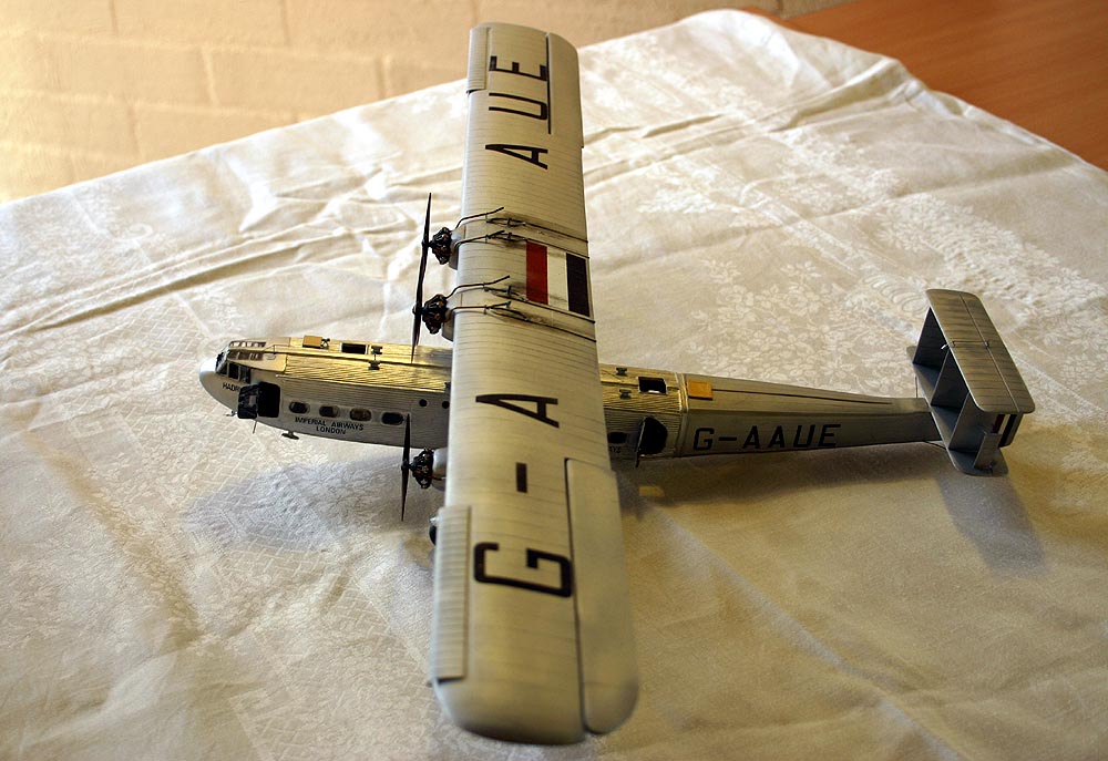 All decals are on the sheet and, despite their age and a few cracks, went on well after being trimmed closely around each major item - I did not want to risk the carrier film between the main letters. I used Solvaset for the lettering on the corrugated surfaces and it worked a treat. The markings should all be slightly glossy as there was no suitable matte paint in those days. All surfaces were then given a couple of coats of FUTURE applied with a large soft brush which,curiously, did make some of the large upper and lower letters and flashes on the flat aluminium finish crinkle a little as the sealer reacted with the decals but short of stripping the whole *!#@**! airframe I will have to live with them, fortunately only visible in certain lights.
Putting It All Together
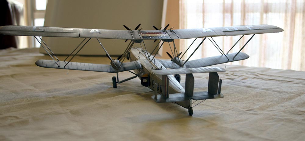
I read and re-read the techniques used by the other modellers and decided I definitely needed a jig of some sort. The strut material included in the kit was not the correct width, being rather too wide - it makes the struts look very clumsy in this scale, the originals give the airframe a more graceful appearance. Fortunately I had enough Contrail struts of the correct width.
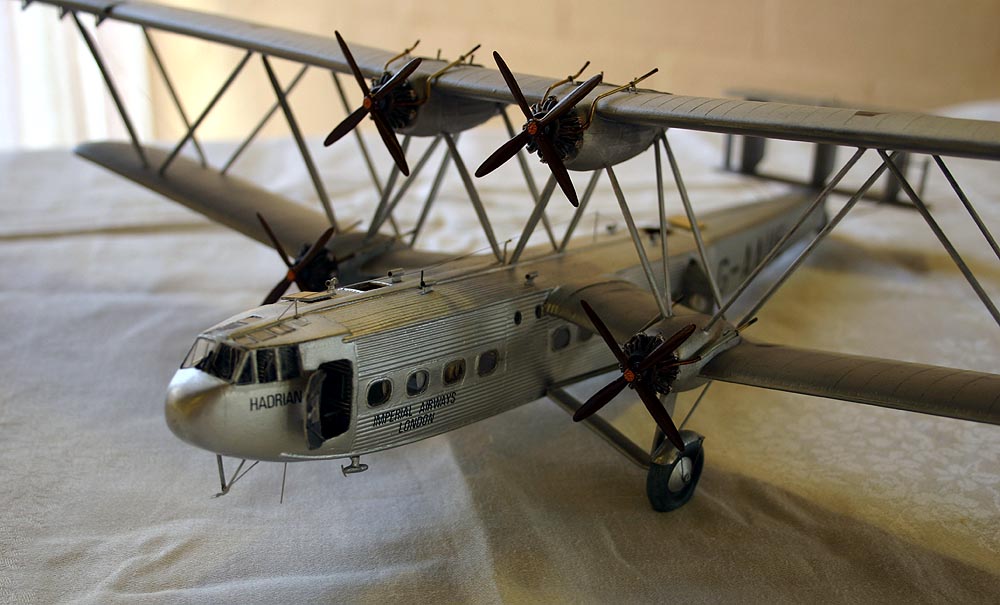 I made another cardboard jig based on the gap between the wings. Each strut has to be cut and sanded to an elegant narrower section at each end as well as being chamfered to match the wing surfaces. The lower end of each strut was drilled to take a small metal pin that went into the holes drilled in the wings surfaces earlier. I started with the two outermost struts on each wing and then did the shorter fuselage to wing ones. This gave a sturdy structure which was then reinforced as all of the other struts were added.
All gluing was with a thick version of superglue. Everything was checked and some touch-up painting completed where necessary and then given a further coat of FUTURE to help with final handling.
Details
The fuselage is littered with fresh air intakes, venturi, pitot tubes, aerials, and curious flag-like thingies under the outer wings and tail actuators all scratch-built from scraps of plastic and added wherever needed. Transparencies were individually cut from clear sheet and glued in place with clear PVA - all 37 panes! I only used PVA for the circular toilet portholes.
The rear wheel came from the scrap box and the kit¹s main wheels were sanded to a better shape as they are far too wide and square in section. I used MILLIPUT to fatten and flatten the area in contact with the ground, remembering to allow for their outward lean on the ground. The distinctive mudguards were press-moulded over the wheels from lead foil, cut to shape, painted and the support wires made from fuse wire and then glued onto the ends of the struts.
The kit engines were pretty awful and the props worse so I contacted Aeroclub, and soon received a lovely set of white metal Bristol Jupiter XI's with propellers. These only needed a small amount of filing and sanding before painting. I had taken a few photos of the real Jupiter in the QANTAS museum in Longreach in Queensland (where it had been used on the QANTAS DH61) so had all the colours to work with. Mid grey crank case, silver cylinders with a black wash, a bit of brass for the valve lifters, black induction pipes on the rear of each cylinder and a burnished silver/black/bronze mix for the extraction pipes and collector ring. The props for the Eastern versions actually had two two-bladers joined together rather than the four-blade prop made by Aeroclub. I filed and sanded two opposite blades near the hub to make them look like they are behind the others. These were painted a dark wood colour with brass bosses.
A great deal of care was taken to make sure that the front faces of the four nacelles are all lined up to make sure that all engines properly lined up in relation to the wing L/E so that the exhausts, from carefully bent 1.25mm brass tubing all fitted over the wings correctly. Each exhaust is attached to the collector ring and has a tiny twisted wire bracket into the wing or nacelle surface. The upper wings were quite messy with exhaust stains and fuel/oil spills (look at the lower photo on p72 of Aeroplane Monthly 11/96).
Finally the tail plane was given some HSS rigging wires,as well as the wires under the tail, as well as the two crossed wires between the outer main-plane struts, the two doors were glued open and roof hatches popped into place.
Conclusion
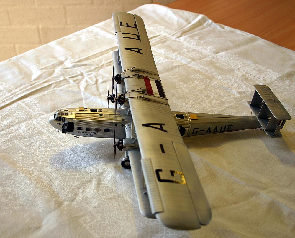 I must admit that I really enjoyed this model and I get quite a kick from the thought that there are probably fewer than a score of them completed around the world, although a resin one will most probably come out in a couple of months!! Despite some of its issues and the eleven months it took to build, the completed beast certainly looks like the original when I 'fly' it around the model room making appropriate radial-engine noises, and that is all I am concerned with. I now have an HP42/45 in my collection.
