Eduard 1/48th Limited Edition Nieuport 16 Profipak
|
 |
For a rundown of the history of this aircraft and the First Look description
of the kit, go to the April
2005 Internet Modeler.
Decisions, Decisions
 This
was one of the most challenging models I have built for a variety of reasons,
many of which have nothing to do with the kit itself. As with any adversity,
my experience with this kit has made me stronger and smarter. It’s
a long story – almost 4,000 words – but, in this review, I
hope to pass along what I learned through my own mistakes. This
was one of the most challenging models I have built for a variety of reasons,
many of which have nothing to do with the kit itself. As with any adversity,
my experience with this kit has made me stronger and smarter. It’s
a long story – almost 4,000 words – but, in this review, I
hope to pass along what I learned through my own mistakes.
At various points along this “journey” I had to make decisions
that had unforeseen repercussions on the building and painting of the
model. The first decision was the easiest for me at the time I made it
but would end up causing the most difficulties later on in the project.
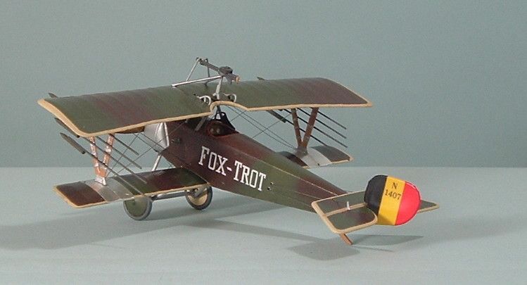
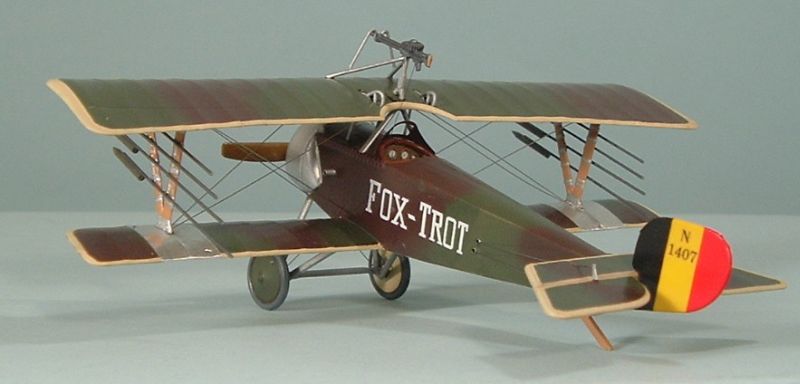
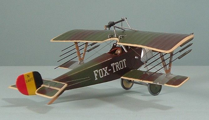
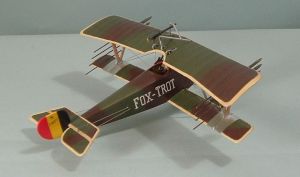
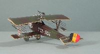
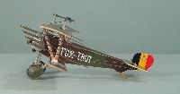
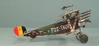
That decision was to build the Belgian “Fox-Trot” version.
This entailed selecting the most complicated camouflage version. It also
began a domino effect of additional decisions that I would not have had
to make had I chosen the simpler, overall aluminum-doped version provided
in the box.
Unlike other kits where you have the luxury of choosing your version
as late as the painting process, with this kit you must make your choice
right at the beginning. Step one offers three different fuselage access
panels for the four aircraft offered on their decal sheets. And once I
made that decision, I was committed to “Fox-Trot” to the very
end.
Fuselage
 Steps
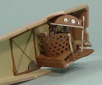
2, 3 and 4 focus on the fuselage interior. I painted the interior Humbrol
Concrete, then bent and assembled the photo etched (PE) interior framework.
It was painted Humbrol Natural Wood and the detail work was picked out
in black, red and aluminum. Due to a lack of any visual evidence to the
contrary, I selected the instrument panel instead of distributing the
PE instrument dials around the cockpit as was done with many early Nieuports.
This consisted of simply sandwiching the decal sheet between two PE pieces
that had already been painted Natural Wood. When it was dry, I dropped
a dollop of MicroScale’s Krystal Kleer on each instrument face.
I followed the instructions in the assembly of the rest of the interior. Steps
2, 3 and 4 focus on the fuselage interior. I painted the interior Humbrol
Concrete, then bent and assembled the photo etched (PE) interior framework.
It was painted Humbrol Natural Wood and the detail work was picked out
in black, red and aluminum. Due to a lack of any visual evidence to the
contrary, I selected the instrument panel instead of distributing the
PE instrument dials around the cockpit as was done with many early Nieuports.
This consisted of simply sandwiching the decal sheet between two PE pieces
that had already been painted Natural Wood. When it was dry, I dropped
a dollop of MicroScale’s Krystal Kleer on each instrument face.
I followed the instructions in the assembly of the rest of the interior.
At this time I began a series of test fittings with the two fuselage
halves. This was complicated with a tab at the rear of the floor piece
and the plastic representation of a metal bar that runs across the cockpit
under the instrument panel, both of which have to be mated with holes
on either side of the fuselage. Frankly, I just couldn’t get the
two sides to close. Therefore, I had to use some putty to fill the cracks
at the top and bottom of the fuselage. I had the same problem with an
Eduard Nieuport 11 that I was building at the same time. I even tried
lopping off the floor board tab, but the sides still refused to come together.
Engine
 I
set the fuselage aside to address the next issue in the instructions –
the engine. This entailed making another decision. As you may remember
from the First Look review, the engine included in the box is the same
engine included in the Nieuport 11 box, which would make it an 80 hp Le
Rhone. I had speculated trading it for the 100 hp Le Rhone included in
the Eduard Nieuport 21 kit, but further research and emails from Internet
Modeler readers had me rethinking that decision. I
set the fuselage aside to address the next issue in the instructions –
the engine. This entailed making another decision. As you may remember
from the First Look review, the engine included in the box is the same
engine included in the Nieuport 11 box, which would make it an 80 hp Le
Rhone. I had speculated trading it for the 100 hp Le Rhone included in
the Eduard Nieuport 21 kit, but further research and emails from Internet
Modeler readers had me rethinking that decision.
 First,
I compared the Nieuport 11 kit instructions with the Nieuport 16 kit instructions
and noticed that Eduard had engineered the kit to allow the 80 hp engine
to be assembled backwards, with the pushrods in the back – one of
the identifying features of a 100 hp Le Rhone. Second, it was pointed
out to me that contemporary pictures of “Fox-Trot” show that
the aircraft was most probably a Nieuport 11, not a 16. First,
I compared the Nieuport 11 kit instructions with the Nieuport 16 kit instructions
and noticed that Eduard had engineered the kit to allow the 80 hp engine
to be assembled backwards, with the pushrods in the back – one of
the identifying features of a 100 hp Le Rhone. Second, it was pointed
out to me that contemporary pictures of “Fox-Trot” show that
the aircraft was most probably a Nieuport 11, not a 16.
Go to the Belgian
Aviation History Association (BAHA) website and scroll down to the
second picture of “Fox-Trot” on the page. Not only are the
pushrods visible on the front of the engine, the engine itself is enclosed
in the Nieuport 11 cowl. Look at the picture beneath it for a proper 100
hp engine and cowl. Suddenly, I was no longer building a Nieuport 16;
I was building a Nieuport 11. Since I was doing a parallel build with
the Eduard Nieuport 11 kit, I decided I would build it as a 16 instead.
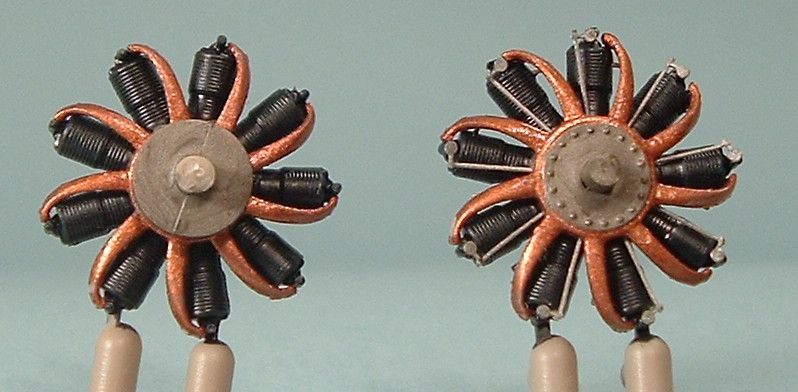
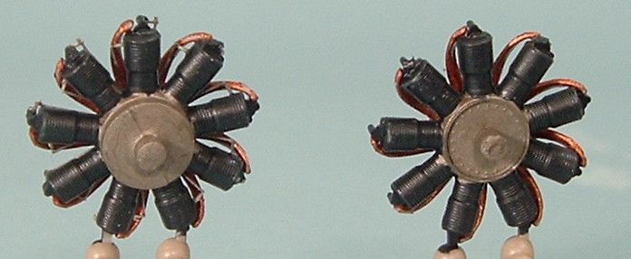
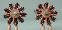
 That
allowed me to assemble the 80 hp engine with Eduard’s PE, since
the pushrods would be visible on the 11. The 100 hp was assembled with
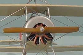
all the other parts from the 16 kit, including the PE engine face. Both
engines were painted with ModelMaster Jet Exhaust for the crankcase and
ModelMaster Gunmetal for the cylinders. Part B-16 (?) was painted copper. That
allowed me to assemble the 80 hp engine with Eduard’s PE, since
the pushrods would be visible on the 11. The 100 hp was assembled with
all the other parts from the 16 kit, including the PE engine face. Both
engines were painted with ModelMaster Jet Exhaust for the crankcase and
ModelMaster Gunmetal for the cylinders. Part B-16 (?) was painted copper.
I deviated from the instructions here and did not attach the engine
to the fuselage until later in the process.
Painting the Major Components
Before I pulled out the airbrush, I attached the lower wing to the fuselage
and glued the headrest to the parallel Nieuport that I was building. Both
required a little putty to fair them into the fuselage. The tail plane
was also attached after drilling out the holes for the control wire to
pass through. At this time, I made the decision to attach the PE control
horns. I wish I hadn’t and would suggest this step be left until
the rigging stage. You’ll understand later.
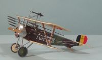
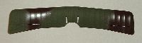
I also cleaned up the upper wing for painting. You must make a decision
at this point regarding the 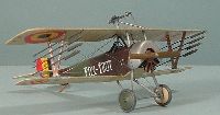 type
of Lewis gun mount you will be using. This kit provides enough parts to
assemble four different types of mounts. Four holes are provided and you
won’t use all of them for any of the types. Once you have chosen
the type of mount, fill in the appropriate hole(s) before painting. Normally,
Eduard provides numbers for which assembly option goes with which aircraft
marking provided in the instructions. Not for this step. Either all four
markings use the first option illustrated for Step 10 or you will have
to conduct your own research of the specific prototype you are modeling.
For “Fox-Trot” I chose the primary option and filled in the
forward centerline hole. type
of Lewis gun mount you will be using. This kit provides enough parts to
assemble four different types of mounts. Four holes are provided and you
won’t use all of them for any of the types. Once you have chosen
the type of mount, fill in the appropriate hole(s) before painting. Normally,
Eduard provides numbers for which assembly option goes with which aircraft
marking provided in the instructions. Not for this step. Either all four
markings use the first option illustrated for Step 10 or you will have
to conduct your own research of the specific prototype you are modeling.
For “Fox-Trot” I chose the primary option and filled in the
forward centerline hole.
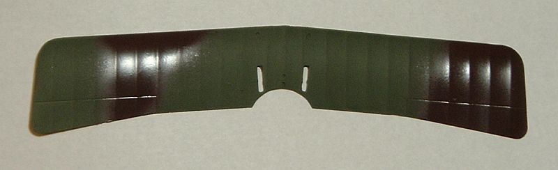
Another decision to be made at this time is the actual colors to be
used for the soft-edged camouflage applied to Nieuports at this time.
We know these colors were dark brown sprayed over dark green. The Windsock
Datafile Special on Nieuport Fighters Part 1 conveniently has Federal
Standard 595a call-outs. The first, FS 20059, is very close to the Gunze
Sangyo H-84 Mahogany recommended for the dark brown by Eduard. The second,
FS 20497, was obviously at typo as that would make it a blue. FS 24097
is more likely as it is a dark green that is very close to PolyScale French
Dark Green. Eduard provides call-outs for Gunze (H-422) and Tamiya (XF-27)
paints, neither of which I could find in my stash or in stock at any local
retailer.
  First,
I painted the undersides Humbrol Ivory. I wanted to use this as I would
eventually have to cover the dark green/brown paint with the underside
color and Humbrol has a good reputation for producing light-colored paints
that cover darker colors in one coat. Then I stuffed the cockpit with
tissue and sprayed the topsides (including the top wing) with the PolyScale
French Dark Green paint. When that dried, I used the pattern suggested
by Eduard to spray on the Gunze Sangyo Mahogany. Then I waited several
days to make sure both paints had dried thoroughly before applying the
Eduard Mask to the top of the upper and lower wings as well as the top
of the tail plane. For the tail plane, I cut slots so I could put the
mask over the control horns. First,
I painted the undersides Humbrol Ivory. I wanted to use this as I would
eventually have to cover the dark green/brown paint with the underside
color and Humbrol has a good reputation for producing light-colored paints
that cover darker colors in one coat. Then I stuffed the cockpit with
tissue and sprayed the topsides (including the top wing) with the PolyScale
French Dark Green paint. When that dried, I used the pattern suggested
by Eduard to spray on the Gunze Sangyo Mahogany. Then I waited several
days to make sure both paints had dried thoroughly before applying the
Eduard Mask to the top of the upper and lower wings as well as the top
of the tail plane. For the tail plane, I cut slots so I could put the
mask over the control horns.
  At
this point I made one more decision while completely forgetting to make
another. After applying the Eduard Mask, I should have sprayed on some
clear overcoat to seal the masking. But I forgot. I decided to apply the
Humbrol Ivory with a hand brush instead of an airbrush. I prefer not to
airbrush enamels as they are so messy in the clean-up process. And I couldn’t
find an acrylic paint that had the coverage quality of the Humbrol paint.
When I removed the mask, it was evident that some of the Humbrol paint
had seeped under the mask in a few places even though I had taken great
pains to brush away from the masked surface. Had I applied the clear top
coat, this seepage may have been averted. Also, if I had airbrushed the
enamel, I may have been able to avoid this blemish. As it was, I had to
remove the blemish with a cotton swab soaked in paint thinner, then go
back and carefully reapply the Humbrol paint. In some cases I had to go
back and reapply the acrylic brown or green paint. At
this point I made one more decision while completely forgetting to make
another. After applying the Eduard Mask, I should have sprayed on some
clear overcoat to seal the masking. But I forgot. I decided to apply the
Humbrol Ivory with a hand brush instead of an airbrush. I prefer not to
airbrush enamels as they are so messy in the clean-up process. And I couldn’t
find an acrylic paint that had the coverage quality of the Humbrol paint.
When I removed the mask, it was evident that some of the Humbrol paint
had seeped under the mask in a few places even though I had taken great
pains to brush away from the masked surface. Had I applied the clear top
coat, this seepage may have been averted. Also, if I had airbrushed the
enamel, I may have been able to avoid this blemish. As it was, I had to
remove the blemish with a cotton swab soaked in paint thinner, then go
back and carefully reapply the Humbrol paint. In some cases I had to go
back and reapply the acrylic brown or green paint.
 It
was at this point that I realized Eduard had left off an important feature.
When I studied photographs of Nieuports with this type of camouflage,
I noticed that not only was the outside rim of the tail plane outlined
in the underside color, but also the edges where the elevators met the
tail plane. It was at this point that I regretted attaching the tail plane
control horns because now I could not mask the area needing paint. Instead,
I had to freehand these straight lines. Even though I used a long-bristled
“Liner” brush, I made several mistakes requiring repeated
applications of paint. The problem was exacerbated by the need to shade
the demarcation between the elevator and tail plane proper. It
was at this point that I realized Eduard had left off an important feature.
When I studied photographs of Nieuports with this type of camouflage,
I noticed that not only was the outside rim of the tail plane outlined
in the underside color, but also the edges where the elevators met the
tail plane. It was at this point that I regretted attaching the tail plane
control horns because now I could not mask the area needing paint. Instead,
I had to freehand these straight lines. Even though I used a long-bristled
“Liner” brush, I made several mistakes requiring repeated
applications of paint. The problem was exacerbated by the need to shade
the demarcation between the elevator and tail plane proper.
At this point I was about ready to give up and offer to buy Internet
Modeler a new kit so that someone else could do the review – but
I persevered. Call me bull-headed.
Decals
 I
had already decided which decals to use, so I just proceeded to apply
them as directed by the instructions. Before applying the decals, I applied
an overall clear gloss spray which revealed a problem that would rear
its head later on. I
had already decided which decals to use, so I just proceeded to apply
them as directed by the instructions. Before applying the decals, I applied
an overall clear gloss spray which revealed a problem that would rear
its head later on.
I had no trouble applying the decals. Even the rudder decals went on
and adhered like paint. This was done by simply spraying the raw plastic
with a clear gloss overcoat, then applying the decal onto the part. The
decal wrapped itself around the part snugly requiring very little touch-up
painting around the edges.
Reflectance Issues
 The
Gunze Sangyo Mahogany paint that I used for the dark brown portion of
the camouflage sprays on gloss. The Polly Scale French Dark Green sprays
on flat. In their original reflectance, they are obviously discernable
as two different colors. When they were over-sprayed so that both colors
were glossy, they lost this discernable difference. In fact, from a couple
of feet away, they looked to be the same. I figured that once I toned
the reflectance down a bit, there would be a wider differentiation. The
Gunze Sangyo Mahogany paint that I used for the dark brown portion of
the camouflage sprays on gloss. The Polly Scale French Dark Green sprays
on flat. In their original reflectance, they are obviously discernable
as two different colors. When they were over-sprayed so that both colors
were glossy, they lost this discernable difference. In fact, from a couple
of feet away, they looked to be the same. I figured that once I toned
the reflectance down a bit, there would be a wider differentiation.
After I applied all the decals I flattened out the reflectance and still
could see very little difference in the colors. My only consolation was
that on the BAHA page, I couldn’t see a difference either. But I
noticed a discrepancy. The BAHA page showed “Fox-Trot’s”
registration number as 1467. Eduard’s decal was 1407. There wasn’t
much I could do about that so I moved on with my construction of the kit.
What I Thought were the Final Assemblies
 After
painting the interplane struts ModelMaster Wood and picked out the fittings
with Testors Silver, I attached the top wing using cyrano acetate (CA)
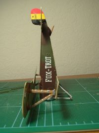
glue. In order to ensure a good alignment I stood the model on its nose,
since it didn’t have its engine attached yet and the leading edge
of the top wing lines up just behind where the cowl attaches to the fuselage. After
painting the interplane struts ModelMaster Wood and picked out the fittings
with Testors Silver, I attached the top wing using cyrano acetate (CA)
glue. In order to ensure a good alignment I stood the model on its nose,
since it didn’t have its engine attached yet and the leading edge
of the top wing lines up just behind where the cowl attaches to the fuselage.
The undercarriage went together without any problems. Then I realized
I had left off the photo etched detail parts. So I had to go back and
add them. I painted the aileron cranks Testors Silver, gluing the straight
piece from fuselage deck to wing and then the big loop into the slot in
the upper wing.
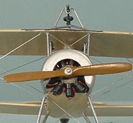
I painted the propeller Humbrol Natural Wood then gave it a coating
of Tamiya Clear Orange. The boss was painted ModelMaster aluminum.
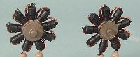
The final piece of the kit that gave me fits was the cowling. This involved
producing a realistic natural metal finish (NMF) – one of the mysteries
of successful model painting. The kit comes with two cowls,   Part
14 for Nieuport 16s and Part 18 for Nieuport 11s. Since I was building
a parallel Nieuport, I used all four cowls for some experimentation and
comparability. Part
14 for Nieuport 16s and Part 18 for Nieuport 11s. Since I was building
a parallel Nieuport, I used all four cowls for some experimentation and
comparability.
I tried several different acrylics sprayed from my airbrush, none of
which were satisfactory. In the past, when building 1/72 models, I had
successfully used Testors Silver. This is not the ModelMaster paint, but
the kind that comes in the small rectangular bottles. However, as I stated
before, I do not like to use enamels in my airbrush. I tried several different
techniques, using several different brushes, but could not get a good
coat laid down without brush marks showing. The difference being that
I had always been able to cover the 1/72 part I was painting with one
swipe. Whenever I had to go back and reswipe the 1/48 scale part, I ended
up with a brush stroke. Eventually, I just broke down and airbrushed the
Testors Silver on. My wife now wonders why the brass stopper in the bathroom
sink is discolored. Any suggestions for helping restore its sheen after
having paint thinner poured over it would be appreciated. The resulting
finish of the cowl still doesn’t look quite good enough to be natural
metal, but it’s close enough.
The Flat Spin
 Up
to this point, I had encountered many challenges in my build. Each one
was dealt with in its own way. The entire project had been a challenge,
not as big a challenge as some other kits, but more than I had expected.
Even so, I was quite happy with my progress and looked forward to making
the finishing touches, attaching the rigging and sending text and pictures
off to Internet Modeler after what I considered a substantial six-month
delay since I first applied paint and glue to the interior parts. However,
my challenging build was about to turn into a difficult build. Up
to this point, I had encountered many challenges in my build. Each one
was dealt with in its own way. The entire project had been a challenge,
not as big a challenge as some other kits, but more than I had expected.
Even so, I was quite happy with my progress and looked forward to making
the finishing touches, attaching the rigging and sending text and pictures
off to Internet Modeler after what I considered a substantial six-month
delay since I first applied paint and glue to the interior parts. However,
my challenging build was about to turn into a difficult build.
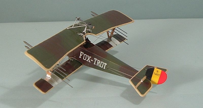
It is advisable to keep checking actual pictures of the prototype that
you are attempting to model. In that vein, I was checking the pictures
on the BAHA page when I noticed something I should have noticed before
I had even started. I should have noticed it before I applied the decals.
The picture of “Fox-Trot” showed that it did not carry the
upper surface top wing roundels as recommended by the Eduard instructions.
 There
is a solution to just about every modeling difficulty. For this case,
I pulled out my can of PolyScale Easy Lift Off (ELO). It wasn’t
the first time I had used the product, so I was familiar with the drill.
I propped the tail up to give me a horizontal surface and used a cotton
swab to liberally apply the ELO to the two upper wing decals. Then I waited
for the decal to start wrinkling. You shouldn’t wait too long because
after a while the ELO will start wrinkling your paint job. When the decals
didn’t start wrinkling in what I thought was an adequate amount
of time, I touched one with the cotton swab. It made a smudge. I dipped
the swab back in the ELO and started scrubbing the decal. It started coming
off like paint. I used several swabs and a soft cloth to dab, dilute and
remove the decals. Then I washed the wing with soap and water. By that
time, the finish was damaged and needed more than just a touch up. There
is a solution to just about every modeling difficulty. For this case,
I pulled out my can of PolyScale Easy Lift Off (ELO). It wasn’t
the first time I had used the product, so I was familiar with the drill.
I propped the tail up to give me a horizontal surface and used a cotton
swab to liberally apply the ELO to the two upper wing decals. Then I waited
for the decal to start wrinkling. You shouldn’t wait too long because
after a while the ELO will start wrinkling your paint job. When the decals
didn’t start wrinkling in what I thought was an adequate amount
of time, I touched one with the cotton swab. It made a smudge. I dipped
the swab back in the ELO and started scrubbing the decal. It started coming
off like paint. I used several swabs and a soft cloth to dab, dilute and
remove the decals. Then I washed the wing with soap and water. By that
time, the finish was damaged and needed more than just a touch up.
 I
backed slowly away from the modeling bench and went to sit in front of
my computer. For some reason or another, I found myself on the BAHA page
once again. And once again I found something I hadn’t noticed before.
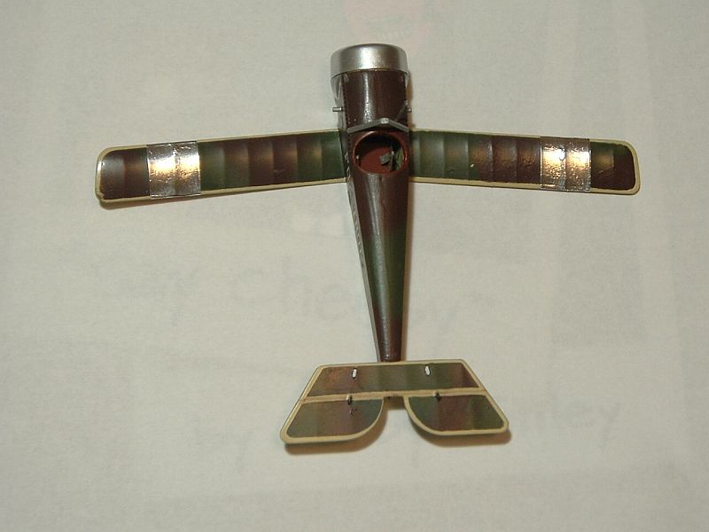
The top picture clearly shows the application of a metal covering to the
lower wings that prevented the fabric from catching fire when the rockets
were launched from the interplane struts. I
backed slowly away from the modeling bench and went to sit in front of
my computer. For some reason or another, I found myself on the BAHA page
once again. And once again I found something I hadn’t noticed before.
The top picture clearly shows the application of a metal covering to the
lower wings that prevented the fabric from catching fire when the rockets
were launched from the interplane struts.
I had already successfully aligned the cabane and interplane struts
and did not want have to do it again. After all, it is one of the most
difficult challenges in assembling a biplane kit. So I came up with a
plan. I would grasp each interplane strut and carefully, with a sharp
knife, pry the strut away from the wing. It was a plan that should have
died the death of most ill-conceived plans. But it didn’t. I was
counting on the fact that the CA glue that I used would be fragile enough
that the part would just pop off, leaving me with properly aligned struts
already attached to a wing that I was going to have to repaint.
 The
plan worked well until the top wing popped off and the model dropped to
the floor. Plastic parts scattered everywhere. The undercarriage came
off, the aileron cranks (all four pieces) scattered across the floor and
the tail skid broke off and completely disappeared. The
plan worked well until the top wing popped off and the model dropped to
the floor. Plastic parts scattered everywhere. The undercarriage came
off, the aileron cranks (all four pieces) scattered across the floor and
the tail skid broke off and completely disappeared.
I felt like I had just entered the modeling equivalent of a flat spin.
My head was certainly spinning. I’ve heard that the best way to
get out of a flat spin is to push the stick forward and apply pressure
to the throttle.
The Dive
I took the can of ELO and headed for the bathroom sink. It was my intent
to remove the paint only from the top wing, leaving the struts attached.
It was just another ill-conceived plan. During the procedure, not only
was the paint on the undersurface of the wing ruined, several of the struts
came off. One of the forward cabane struts managed to find its way down
the drain. One of the interplane struts came off with a piece of roundel
attached to it.
 After
removing/salvaging the remaining struts, I took all the paint off the
upper wing. While using a toothbrush to scrub the last recalcitrant specks
of paint, I ended up somehow chipping the trailing edge of the wing. Later,
with all the paint removed, I started reaming the strut locator holes
with a motor tool to remove the residual glue. At one hole, I drilled
all the way through the wing. I made a mental note that it was probably
not a good decision to clean a hole with a motor tool. After
removing/salvaging the remaining struts, I took all the paint off the
upper wing. While using a toothbrush to scrub the last recalcitrant specks
of paint, I ended up somehow chipping the trailing edge of the wing. Later,
with all the paint removed, I started reaming the strut locator holes
with a motor tool to remove the residual glue. At one hole, I drilled
all the way through the wing. I made a mental note that it was probably
not a good decision to clean a hole with a motor tool.
I was out of the spin and in a full power dive. It seemed to me I had
only made things worse – and that things were going to get worse
before they got better, if they were going to get better at all. I was
tempted to just let the project reach impact, but I fought the aileron
compression, pulled back on the stick as hard as I could and tried to
level out before I ran out of sky.
Leveling Off
The first thing I did was let IM know what was going on. Editor Matt
Bittner was supportive. Next, I wrote Eduard and let them know that I
needed a new set of decals.
 I
removed the forward cabane struts from the parallel kit that I was building,
replacing them with Contrail strut material. I would use the Eduard struts
on the kit I was building for IM. I
removed the forward cabane struts from the parallel kit that I was building,
replacing them with Contrail strut material. I would use the Eduard struts
on the kit I was building for IM.
Using a technique I learned from the World War I Modeling Mailing List,
I fixed the chip in the wing trailing edge. First, I covered the area
that needed to be filled in by putting Scotch Tape on the upper surface.
Next, I filled the chipped area with CA glue. When the glue dried, I removed
the tape and sanded the repair until it blended into the kit part. Similarly,
the hole in the wing was filled with putty and smoothed flush with the
kit part using acetone. I had to fashion a new tail skid with evergreen
strip styrene, the only part of the finished model (besides the rigging)
that didn’t come from the manufacturer.
Since I was repainting the wing, I used the opportunity to seal the
Eduard Mask with a clear topcoat to insure that the border paint wouldn’t
seep under the mask. Not only did that technique not work, it created
a little dried bubble of clear paint that had to be sanded away. Once
again, I used cotton swabs soaked in paint thinner to clean up the paint
that seeped under the mask. I finished up by sealing the wing with ModelMaster
semi-gloss paint sprayed out of a can.
 It
took two months for Eduard to send the replacement decal sheet. The roundels
and stenciling was applied and sealed with the semi-gloss paint. I waited
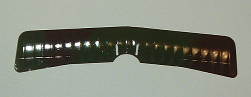
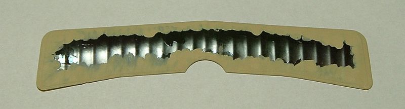
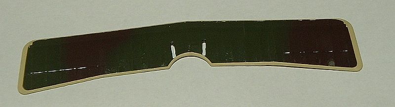
a week before attempting to attach the upper wing to the model. Before
doing this, however, I used ModelMaster foil to replicate the metal sheets
under each interplane strut that protected the fabric surfaces from the
rocket flames. Then I used CA to glue the cabane struts to the fuselage,
the interplane struts to the upper wing and then the upper wing to the
cabane struts. I waited for all this to dry before using CA to glue the
interplane struts to the lower wing. It
took two months for Eduard to send the replacement decal sheet. The roundels
and stenciling was applied and sealed with the semi-gloss paint. I waited
a week before attempting to attach the upper wing to the model. Before
doing this, however, I used ModelMaster foil to replicate the metal sheets
under each interplane strut that protected the fabric surfaces from the
rocket flames. Then I used CA to glue the cabane struts to the fuselage,
the interplane struts to the upper wing and then the upper wing to the
cabane struts. I waited for all this to dry before using CA to glue the
interplane struts to the lower wing.
Landing
 The
rigging, with .008 stainless steel wire from a company called Small Parts,
went much smoother than the building of the rest of the kit. I only had
to crawl around on the floor about four times hunting lengths of wire
that pinged out of my tweezers. The wire was attached with CA glue. When
the rigging was complete, I oversprayed the model once again with semi-gloss
out of the can. The
rigging, with .008 stainless steel wire from a company called Small Parts,
went much smoother than the building of the rest of the kit. I only had
to crawl around on the floor about four times hunting lengths of wire
that pinged out of my tweezers. The wire was attached with CA glue. When
the rigging was complete, I oversprayed the model once again with semi-gloss
out of the can.
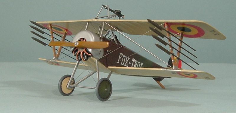
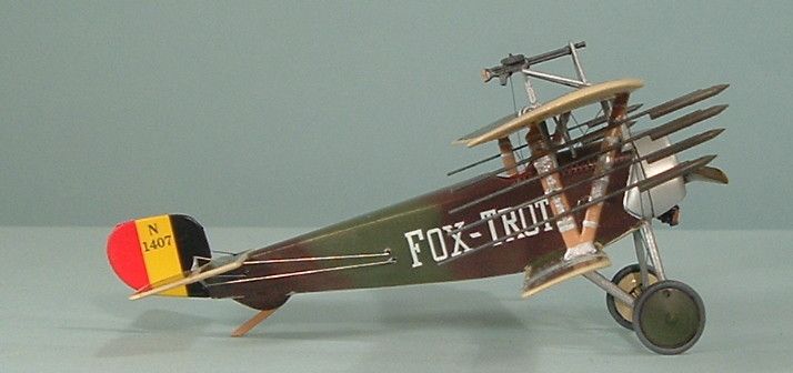
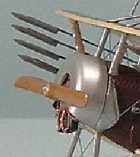
After a quick check of the prototype’s picture when I realized
I wasn’t quite finished yet. I had eight rockets to attach to the
interplane struts. Although all the rockets are listed as “Part
4” there are four different pairs. Each rocket has two nubs spaced
to fit into holes in the interplane struts. This procedure took a lot
longer than I thought it would and was interrupted by a roof leak during
a major storm. To make what is already a very long story somewhat shorter,
I found that the best way to attach the rockets was to allow a puddle
of CA to gel by letting it air out for a few minutes. Then I applied a
small drop of the gel to the strut holes and affixed the rockets by matching
the nubs to the holes. I worked from the bottom down. I checked around
for any parts I hadn’t applied and found the PE windscreen lying
off to one side. Using the 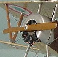 clear
plastic part as a template, I bent it into the appropriate curvature and
CAed it onto the fuselage. I checked around again, found no extraneous
parts and, one year after I submitted the in-box review to IM, declared
the build finished. clear
plastic part as a template, I bent it into the appropriate curvature and
CAed it onto the fuselage. I checked around again, found no extraneous
parts and, one year after I submitted the in-box review to IM, declared
the build finished.
I’m going to take some time off, mainly because we are getting
ready to move and I’m going to have to pack away all my modeling
supplies and equipment. But I also need some time to develop a hunger
for modeling. This particular project has been a little unappetizing.
Thanks to Eduard for the kit. |
|