The Ship's Camel:
Building the Eduard Sopwith Camel 2F1 in 1/48 Scale
|
 |
History
A brief history of the Sopwith Camel 2F1 is included in the First
Look Preview in the February Internet Modeler, so I will just add
a few words about the particular aircraft I chose to model. As mentioned
in the preview, the kit I received is a pre-production test shot, which
came without instructions, decals, or a box with boxart. After some deliberation
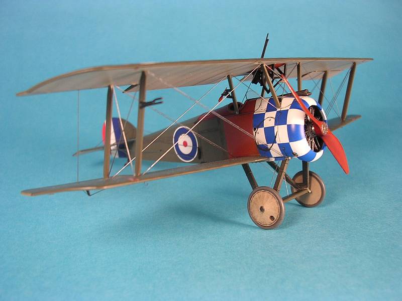
I chose to build the kit in the markings of a blue and white checkered
aircraft as flown by Captain Bernard Arthur Smart from HMS Furious in
1918. This aircraft was one of seven launched from HMS Furious on July
19, 1918 as part of the first carrier air strike in history, the target
being the Zeppelin base at Tondern. The aircraft were specially configured
for the mission with bomb racks and bomb sights, and the Lewis guns were
left behind to save weight. The raid was a success with two Zeppelins
being destroyed in their sheds by the 50-pound bombs dropped by the Camels.
Only two of the Camels managed to return to Furious, one of which was
Smart's aircraft. Captain Smart was awarded the Distinguished Service
Order for this exploit.
Construction
 As
mentioned the kit came without instructions (Bah, who needs instructions,
anyway?). Luckily I already had an example of the Camel F1 kit, so the
instructions from this kit came in very handy during the build. I also
happened to have the Windsock Datafile for the 2F1, which proved indispensable
while I was trying to puzzle together the various details in this kit.
This Datafile also has a very fine profile of Smart's aircraft on the
cover by Ray Rimell and drawings within by Ian Stair. As
mentioned the kit came without instructions (Bah, who needs instructions,
anyway?). Luckily I already had an example of the Camel F1 kit, so the
instructions from this kit came in very handy during the build. I also
happened to have the Windsock Datafile for the 2F1, which proved indispensable
while I was trying to puzzle together the various details in this kit.
This Datafile also has a very fine profile of Smart's aircraft on the
cover by Ray Rimell and drawings within by Ian Stair.
Overall fit of the parts is excellent. Curiously there was a very slight
ridge of material along the edges of many of the parts, which has to be
removed to ensure a good fit. This was easily accomplished with a few
swipes with a sanding stick in most cases. Many of the smaller parts are
very fine and delicate, and require great care while removing them from
the sprues to prevent breakage.
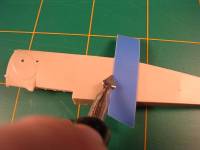
I began by preparing the fuselage halves to include the details peculiar
to the 2F1. This meant scribing a line where the fuselage separates as
well as filling in the side step and moving it forward of this line. A
hole was drilled in the proper location for the external elevator bellcranks
as per the drawings in the Datafile. As the 2F1 normally carried only
one Vickers, the ejector port on the right side of the fuselage needs
to be filled in. The kit provides a part to plug this hole, which when
cemented and sanded flush does the job.
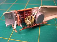 Construction
of the cockpit then began in earnest. The instrument panel and other interior
wood structures were prepared by painting them a wood color. Everyone
has their favorite method of recreating wood with paints. My method involves
painting the area first with Tamiya acrylic XF-59 Desert Yellow thinned
with Future. When this is dry a thin streaky coat of Testors ModelMaster
Burnt Sienna or Raw Umber enamel is applied with a Filbert tipped brush
to impart a wood grain effect. Then if desired a seal coat of Gunze Clear
Orange and/or Clear Yellow thinned with Future is airbrushed on in very
thin coats to get the desired varnished effect. Sometimes just a coat
of clear is all that is required. Construction
of the cockpit then began in earnest. The instrument panel and other interior
wood structures were prepared by painting them a wood color. Everyone
has their favorite method of recreating wood with paints. My method involves
painting the area first with Tamiya acrylic XF-59 Desert Yellow thinned
with Future. When this is dry a thin streaky coat of Testors ModelMaster
Burnt Sienna or Raw Umber enamel is applied with a Filbert tipped brush
to impart a wood grain effect. Then if desired a seal coat of Gunze Clear
Orange and/or Clear Yellow thinned with Future is airbrushed on in very
thin coats to get the desired varnished effect. Sometimes just a coat
of clear is all that is required.
The fabric areas of the interior were painted Gunze H85 Sail Color acrylic,
and the bare metal areas Citadel Chain Mail acrylic. All the acrylic paints
that were sprayed were thinned with Future to give a smooth finish and
to enhance strength and adhesion.
The instrument bezels were picked out with Testors ModelMaster Acryl
Interior Black paint, and Reheat instrument dials were used for the instrument
faces. A drop of Future on each then 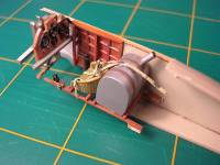 represented
the glass face. The seat comes as either a solid plastic part, or as a
base with a rim for a photoetched weaved back which is included in the
Profipack kits. The F1 kit I have comes with a set of decals to recreate
the weave for the solid seat, so I decided to try them. I painted the
seat in the wood effect as described, and then applied the decals. I thought
the contrast of the black decal and the seat was too stark so I applied
a thin transparent layer of Desert Yellow over it to mute it down. Seatbelts
were provided from the Eduard WWI RFC Seatbelt set, which were painted
Citadel Bleached Bone, a good webbing color. The fuel tanks behind the
seat are a nice touch. These were painted with Citadel Chain Mail and
straps added with brown-painted clear decal film cut in narrow strips.
Some care is required to align the filler pipe on the main fuel tank with
the hole in the turtledeck. Mine did not line up, so I would suggest adding
the pipe after the fuselage is assembled. represented
the glass face. The seat comes as either a solid plastic part, or as a
base with a rim for a photoetched weaved back which is included in the
Profipack kits. The F1 kit I have comes with a set of decals to recreate
the weave for the solid seat, so I decided to try them. I painted the
seat in the wood effect as described, and then applied the decals. I thought
the contrast of the black decal and the seat was too stark so I applied
a thin transparent layer of Desert Yellow over it to mute it down. Seatbelts
were provided from the Eduard WWI RFC Seatbelt set, which were painted
Citadel Bleached Bone, a good webbing color. The fuel tanks behind the
seat are a nice touch. These were painted with Citadel Chain Mail and
straps added with brown-painted clear decal film cut in narrow strips.
Some care is required to align the filler pipe on the main fuel tank with
the hole in the turtledeck. Mine did not line up, so I would suggest adding
the pipe after the fuselage is assembled.
The 2F1 was powered by the Bentley B. R. I, but the kit only provides
the Clerget. I decided to 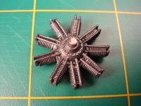 use
the Clerget as provided due to time constraints but the modeler can modify
the kit engine to look more like a Bentley if desired. The parts for the
pushrods are very delicate and fiddly, and I broke several when removing
them from the sprue. The missing broken ones were replaced with stretched
sprue. On future Camel builds I think I will replace all the push rods
with sprue from the outset, as it looks cleaner. The finished engine was
painted gunmetal and given a wash of flat black, then mounted on the firewall
with the retaining pin provided. This allows the engine to turn freely
on the firewall, as a rotary should. use
the Clerget as provided due to time constraints but the modeler can modify
the kit engine to look more like a Bentley if desired. The parts for the
pushrods are very delicate and fiddly, and I broke several when removing
them from the sprue. The missing broken ones were replaced with stretched
sprue. On future Camel builds I think I will replace all the push rods
with sprue from the outset, as it looks cleaner. The finished engine was
painted gunmetal and given a wash of flat black, then mounted on the firewall
with the retaining pin provided. This allows the engine to turn freely
on the firewall, as a rotary should.
All the various interior subassemblies were now brought together and
the fuselage halves cemented together. The joint was sanded smooth, but
I obliterated some of the sunken fabric detail on the turtle deck while
trying to eliminate some stubborn sprue gate areas. The lower wing and
firewall 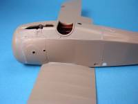 was
mounted to the fuselage after a very slight amount of trimming of the
joining areas. A very good fit resulted. I used just a very small amount
of filler to eliminate the lower joints. As the engine was mounted on
the firewall that formed part of the fuselage structure I decided to install
the cowling to protect the vulnerable engine and to facilitate painting
of the blue and white checkers later. Here I ran into a bit of trouble
as the cowling was just slightly narrower than the fuselage and sat slightly
right of center. I trimmed and sanded the inside of the cowl on the right
side and trimmed the firewall on the left side, so that the cowl lined
up a little better, but it still was not perfect (Eduard is already aware
of this problem and are making the necessary corrections for the production
kit). One effect was that the inside of the cowl now fouled the engine
and would not allow it to turn. Oh well. The remaining joints were cleaned
up and a few areas filled in with Mr. Surfacer 500 where required. was
mounted to the fuselage after a very slight amount of trimming of the
joining areas. A very good fit resulted. I used just a very small amount
of filler to eliminate the lower joints. As the engine was mounted on
the firewall that formed part of the fuselage structure I decided to install
the cowling to protect the vulnerable engine and to facilitate painting
of the blue and white checkers later. Here I ran into a bit of trouble
as the cowling was just slightly narrower than the fuselage and sat slightly
right of center. I trimmed and sanded the inside of the cowl on the right
side and trimmed the firewall on the left side, so that the cowl lined
up a little better, but it still was not perfect (Eduard is already aware
of this problem and are making the necessary corrections for the production
kit). One effect was that the inside of the cowl now fouled the engine
and would not allow it to turn. Oh well. The remaining joints were cleaned
up and a few areas filled in with Mr. Surfacer 500 where required.
Finishing and Decals
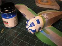
I began painting the airframe by painting the blue and white checker
pattern on the nose. This was accomplished in three stages, first with
a coat of Testors ModelMaster Acryl Semi Gloss White 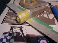 sprayed
over the entire area. When this was cured I masked off one row of squares
with Tamiya masking tape, then sprayed Testors ModelMaster Acryl French
Blue. When this was dry I then masked off the remaining rows of squares
and sprayed them blue as well. This involves a little extra effort but
the result is well worth the time spent. Once this was dry I masked off
the entire checkered area and prepared the model for the remaining colors. sprayed
over the entire area. When this was cured I masked off one row of squares
with Tamiya masking tape, then sprayed Testors ModelMaster Acryl French
Blue. When this was dry I then masked off the remaining rows of squares
and sprayed them blue as well. This involves a little extra effort but
the result is well worth the time spent. Once this was dry I masked off
the entire checkered area and prepared the model for the remaining colors.
The rudder and elevators have control horns molded on which I did not
like, so I trimmed them off and replaced them with photoetched horns from
the PART Horns and Turnbuckles set. The elevators' torque tube connecting
them is extremely thin and delicate, and despite all my efforts the elevator
assembly broke in two.
For some unknown reason the kit comes with ten ailerons, of which of
course only four are needed. These were cleaned up and control horns attached.
The control surfaces fit very well to their respective flying surfaces,
with a light press-fit in most cases.
 The
raised rib tape detail on the kit is fairly evident. Upon examining photos
of the real airplane this appears to be the case, so I left them as is.
The kit includes clear parts for the transparent wing inspection panels.
These were cemented in place after the insides of which were painted Burnt
Sienna to indicate the wood interior framework. These were then masked
off with Tamiya tape in preparation for painting. The
raised rib tape detail on the kit is fairly evident. Upon examining photos
of the real airplane this appears to be the case, so I left them as is.
The kit includes clear parts for the transparent wing inspection panels.
These were cemented in place after the insides of which were painted Burnt
Sienna to indicate the wood interior framework. These were then masked
off with Tamiya tape in preparation for painting.
The landing gear struts were assembled but I thought they looked a little
bare so I added bungee chord shock absorbers made from cotton thread fixed
with superglue. Unfortunately the main wheel double axle is molded into
the spreader. For a characteristic Sopwith "Sit" with the wheels
splayed out some modification would be required. Perhaps a pair of axles
of brass tubing or rod would be in order. I just decided to build them
as supplied and carry on. The wheel covers were painted Gunze Sail Color
and the tyres masked off with Tamiya tape cut in arcs with an Olpha compass
cutter. The tyres were then painted dark grey.
The color scheme applied would be the ubiquitous PC10 over Clear Doped
Linen (CDL). I decided to preshade some areas in order to break up the
potential monotony of the finish, and to 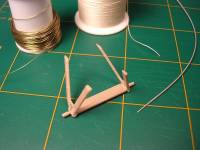 add
some depth and dimension. The upper surfaces were preshaded with black
and the lower surfaces preshaded with dark earth. I also masked off the
rib locations along the fuselage. The lower surfaces were then sprayed
with several light coats of Gunze 85 Sail Color, subtly allowing the preshading
to show through. The upper surfaces were sprayed in the same way with
Gunze H421 RLM 81 Braun Violet, as good a match for PC10 as any (PC10
could vary from olive drab to chocolate brown or anything in between).
I was quite happy with the final result. PC10 was also applied to the
landing gear strut assembly and to the interplane and cabane struts. The
little Rotherham pump on the right rear cabane was picked out with black
and drybrushed aluminum. The pump propeller was painted using the wood
method mentioned, as was the main propeller, with the hub detailed with
Citadel Boltgun Metal (The Citadel range of acrylic paints have some rather
bizarre names but they are among the finest acrylic paints I have used
to date). The wooden panels on the fuselage were painted wood as well
in the same manner. The masking tape came off the checkerboard and a few
areas touched up with a brush. The cockpit coaming was then painted Humbrol
Red Leather. add
some depth and dimension. The upper surfaces were preshaded with black
and the lower surfaces preshaded with dark earth. I also masked off the
rib locations along the fuselage. The lower surfaces were then sprayed
with several light coats of Gunze 85 Sail Color, subtly allowing the preshading
to show through. The upper surfaces were sprayed in the same way with
Gunze H421 RLM 81 Braun Violet, as good a match for PC10 as any (PC10
could vary from olive drab to chocolate brown or anything in between).
I was quite happy with the final result. PC10 was also applied to the
landing gear strut assembly and to the interplane and cabane struts. The
little Rotherham pump on the right rear cabane was picked out with black
and drybrushed aluminum. The pump propeller was painted using the wood
method mentioned, as was the main propeller, with the hub detailed with
Citadel Boltgun Metal (The Citadel range of acrylic paints have some rather
bizarre names but they are among the finest acrylic paints I have used
to date). The wooden panels on the fuselage were painted wood as well
in the same manner. The masking tape came off the checkerboard and a few
areas touched up with a brush. The cockpit coaming was then painted Humbrol
Red Leather.
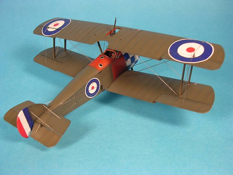
This sample kit did not come with decals, so I had to go to another
source. I had the Aeromaster 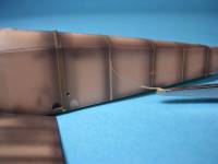 sheet
48081 "Camels Part I" which were used. The markings on this
Camel are very simple, consisting of only white edged roundels on all
six locations and the rudder tricolor. These went on with no problems
after giving the areas a gloss coat of Future where they were to go. My
only complaint is that the blue is too dark in my opinion, RFC Roundel
Blue being quite a bit lighter during this period. When the decals were
in place and dry they were sealed with a coat of Future. A very light
wash of a thinned mixture of Testors Raw Umber and Flat Black enamels
was applied sparingly around the cowling, wing panel joints, and the wing
root areas. The wheels and tyres were weathered a bit heavier, as I thought
they would pick up a lot more grunge. When all was dry a few thin coats
of Testors Acryl Semi Gloss Clear was applied to kill the shine. sheet
48081 "Camels Part I" which were used. The markings on this
Camel are very simple, consisting of only white edged roundels on all
six locations and the rudder tricolor. These went on with no problems
after giving the areas a gloss coat of Future where they were to go. My
only complaint is that the blue is too dark in my opinion, RFC Roundel
Blue being quite a bit lighter during this period. When the decals were
in place and dry they were sealed with a coat of Future. A very light
wash of a thinned mixture of Testors Raw Umber and Flat Black enamels
was applied sparingly around the cowling, wing panel joints, and the wing
root areas. The wheels and tyres were weathered a bit heavier, as I thought
they would pick up a lot more grunge. When all was dry a few thin coats
of Testors Acryl Semi Gloss Clear was applied to kill the shine.
Final Assembly and Rigging
After examining the many photos in the Datafiles and elsewhere I could
not resist the temptation to add a few extra details to the model. These
included a pitot tube on the right forward interplane strut made out of
brass wire, a windscreen cut out of a sheet of 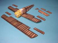 Evergreen
.010" clear styrene stock, and picquet rings made of brass bead wire
twisted into an eyelet. The Vickers gun as supplied in the kit was a little
bare so I added a photoetched cocking handle from a leftover Eduard Sopwith
Triplane set. Strangely the Vickers gun comes in two parts, presumably
to aid installation into the cowling, but I assembled this one and painted
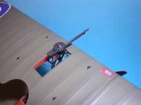
it completely before installing it and it fit very well. The very delicate
Lewis gun and its unique Admiralty Top Plane Mounting was puzzled together
from the parts supplied with the kit and from examining available photos.
This was later mounted on the top wing so that it could swivel up and
down: A little finicky, but the final result was worth the effort. The
external elevator bellcranks were added as were the attaching fittings
for the fuselage joint made out of short lengths of Evergreen stock painted
black. Too late I realized there were lifting brackets on the top wing
center section, so I added these with some black decal film cut into tiny
triangles, but they are probably better made with thin card or brass sheet
stock. They still look OK, I think. Evergreen
.010" clear styrene stock, and picquet rings made of brass bead wire
twisted into an eyelet. The Vickers gun as supplied in the kit was a little
bare so I added a photoetched cocking handle from a leftover Eduard Sopwith
Triplane set. Strangely the Vickers gun comes in two parts, presumably
to aid installation into the cowling, but I assembled this one and painted
it completely before installing it and it fit very well. The very delicate
Lewis gun and its unique Admiralty Top Plane Mounting was puzzled together
from the parts supplied with the kit and from examining available photos.
This was later mounted on the top wing so that it could swivel up and
down: A little finicky, but the final result was worth the effort. The
external elevator bellcranks were added as were the attaching fittings
for the fuselage joint made out of short lengths of Evergreen stock painted
black. Too late I realized there were lifting brackets on the top wing
center section, so I added these with some black decal film cut into tiny
triangles, but they are probably better made with thin card or brass sheet
stock. They still look OK, I think.
The airframe was prepared for rigging by drilling holes with a #80 twist
drill in all the appropriate locations. The top wing was attached by first
fixing the interplane struts to the lower wings with Tamiya Extra Thin
Cement. A simple jig was constructed using foam core illustration board
to which was glued a sheet of graph paper. A few blocks of balsa glued
to this surface helps keep everything 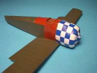 aligned.
When the struts were dry enough the top wing was installed very carefully
again using Tamiya Extra Thin Cement. I went off to watch TV for a while
during which various paint jars and such held everything in proper alignment
until the glue dried. The struts were then fixed in place and reinforced
with a drop of thin superglue. Next the cabane struts were attached. Here
I ran into a little problem as the front cabanes were very slightly short,
and the rear cabanes were too long by about 1mm. I just trimmed them to
fit and all was well. Upon reflection, I believe the interplane struts
are mislabeled in the (Camel F1) instructions. B-19 which are the forward
interplane struts are longer than B-9, the rear struts. I think if one
used the shorter struts forward this would take care of the cabane problem. aligned.
When the struts were dry enough the top wing was installed very carefully
again using Tamiya Extra Thin Cement. I went off to watch TV for a while
during which various paint jars and such held everything in proper alignment
until the glue dried. The struts were then fixed in place and reinforced
with a drop of thin superglue. Next the cabane struts were attached. Here
I ran into a little problem as the front cabanes were very slightly short,
and the rear cabanes were too long by about 1mm. I just trimmed them to
fit and all was well. Upon reflection, I believe the interplane struts
are mislabeled in the (Camel F1) instructions. B-19 which are the forward
interplane struts are longer than B-9, the rear struts. I think if one
used the shorter struts forward this would take care of the cabane problem.
The Camel has double flying wires, which were done with invisible nylon
mending thread fixed with superglue. The remaining rigging and control
cables were done with heat stretched sprue attached with white PVA glue.
The little "Acorn" fitting between the cowl and the top wing
was fabricated from the end of a pointed round toothpick cut and sanded
to shape then reinforced with thin superglue. A small jig helped to attach
the two uppermost wires, which were superglued to the acorn. This assembly
was mounted on the top wing underside. Then it was simply a matter of
attaching the two lower wires with white glue.
 All
remaining bits and pieces were installed including the Vickers, propeller,
tailskid, and the wheels, which I gave a slight splay to mimic the sit
of the original, despite the axles not being so. Suddenly, it seemed,
the model was finished! All
remaining bits and pieces were installed including the Vickers, propeller,
tailskid, and the wheels, which I gave a slight splay to mimic the sit
of the original, despite the axles not being so. Suddenly, it seemed,
the model was finished!
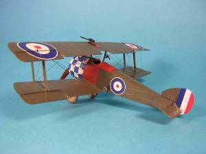
Conclusion
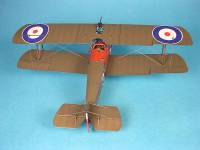
Seldom do
I catch myself grinning while building a model, but I did on several occasions
while building this one! Despite the few minor setbacks (most of which
were self-inflicted) and minor shortcomings of the kit, I had a great
time building it. The finished result is a convincing replica of this
pugnacious looking little fighter.
I understand that the kit will be officially released onto the market
sometime this spring, with improvements over this test sample. A Profipack
version will most certainly soon be available, which will include many
of the details in either photoetch or resin that I scratchbuilt into this
one.
Thanks to Eduard for the review
sample, and very special thanks to Matt Bittner for allowing me to build
this kit and for the continued words of encouragement throughout! Thanks
also to the wonderful folks on the WWI Modelers Discussion Forum for their
support and inspiration.
References
 Sopwith
2F1 Camel, Windsock Datafile No. 6, J.M. Bruce, Albatros Productions Ltd.,
1987 Sopwith
2F1 Camel, Windsock Datafile No. 6, J.M. Bruce, Albatros Productions Ltd.,
1987
Sopwith Camel, Windsock Datafile No. 26, J.M. Bruce, Albatros Productions
Ltd., 1991
The Camel Fighter, John Pudney, Hamish Hamilton Ltd., 1964
WWI British Aeroplane Colours and Markings, Bruce Robertson, Albatros
Productions Ltd., 1996
Sopwith Fighters in Action, Peter Cooksley, Squadron Signal Publications,
1991
There is also an invaluable collection of Sopwith Camel photos on the
WWI Modelers
Website, many of which are of the 2F1.
|
|