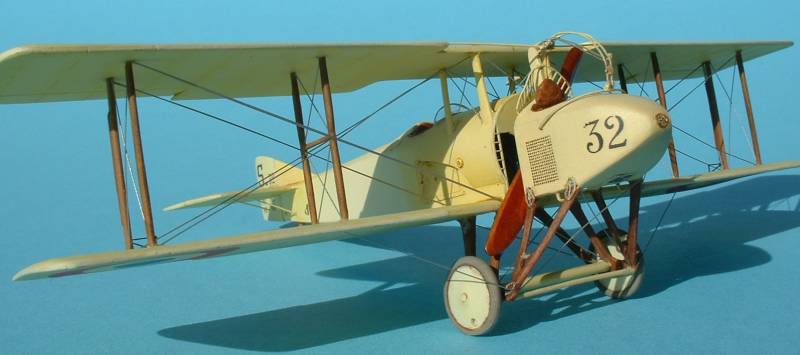
Amodel 1/72nd SPAD A.2
|
 |
History
I won't delve too much into the history of the SPAD 'pulpits' suffice
to say it was an interesting solution to the problem of having the gun
fire in front of the propeller, prior to the invention of the synchronizer
gear. The French and Russians were the primary users, and only the Russians
kept flying them long into (and after) WW1.
 One
thing to mention right up front. The SPAD A.2 drawings in the Mini-Datafile
are wrong. I measured them against all published specifications (luckily
all references agree), and the drawings just don't match up. The odd thing
is that the A.4 drawings in the same book are fine. One
thing to mention right up front. The SPAD A.2 drawings in the Mini-Datafile
are wrong. I measured them against all published specifications (luckily
all references agree), and the drawings just don't match up. The odd thing
is that the A.4 drawings in the same book are fine.
The Kit
The kit consists of 41 injected plastic pieces with only one decal option
for the overdone "Ma Jeanne". Amodel has also released this
as the A.4 with the different wings and tail, as well as an A.4 version
with skis.
Construction
The name of the game with this kit is Thin! Thin! Thin! Thin the undersides
of the flying surfaces to bring them more into scale. (To be truthful,
I don't think I thinned the wings enough.) Thin the "cheeks"
that sit at the side of the fuselage behind the engine. Thin the main
struts - center and undercarriage, at least. Either thin some of the smaller
pieces or replace them as needed.
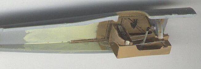
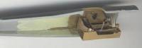 Naturally
construction starts with the cockpit. While the insides probably could
be thinned to be more in-scale, it's not needed as once the fuselage is
closed up it will be difficult to tell how thick the sidewalls are. Since
the cockpit that comes with the kit is poorly represented, I scratchbuilt
most of the cockpit - outside of the sidewall detail (which is what's
provided with the kit). The "floor" - per se - isn't where the
seat sets (regardless of the Amodel instructions). There is a "shelf-like"
structure that the seat sets on which is basically two curved sides that
meets the part that the seat sets on. Difficult to actually describe so
refer to the supplied photo of my built-up cockpit. The kit comes with
rudder pedals but not a control stick, which was also scratchbuilt. In
addition I added some rigging that would be visible from the outside of
the cockpit. I used the kit's "instrument panel" as well as
the firewall. The seat was replaced with a resin replacement from Rosemont. Naturally
construction starts with the cockpit. While the insides probably could
be thinned to be more in-scale, it's not needed as once the fuselage is
closed up it will be difficult to tell how thick the sidewalls are. Since
the cockpit that comes with the kit is poorly represented, I scratchbuilt
most of the cockpit - outside of the sidewall detail (which is what's
provided with the kit). The "floor" - per se - isn't where the
seat sets (regardless of the Amodel instructions). There is a "shelf-like"
structure that the seat sets on which is basically two curved sides that
meets the part that the seat sets on. Difficult to actually describe so
refer to the supplied photo of my built-up cockpit. The kit comes with
rudder pedals but not a control stick, which was also scratchbuilt. In
addition I added some rigging that would be visible from the outside of
the cockpit. I used the kit's "instrument panel" as well as
the firewall. The seat was replaced with a resin replacement from Rosemont.
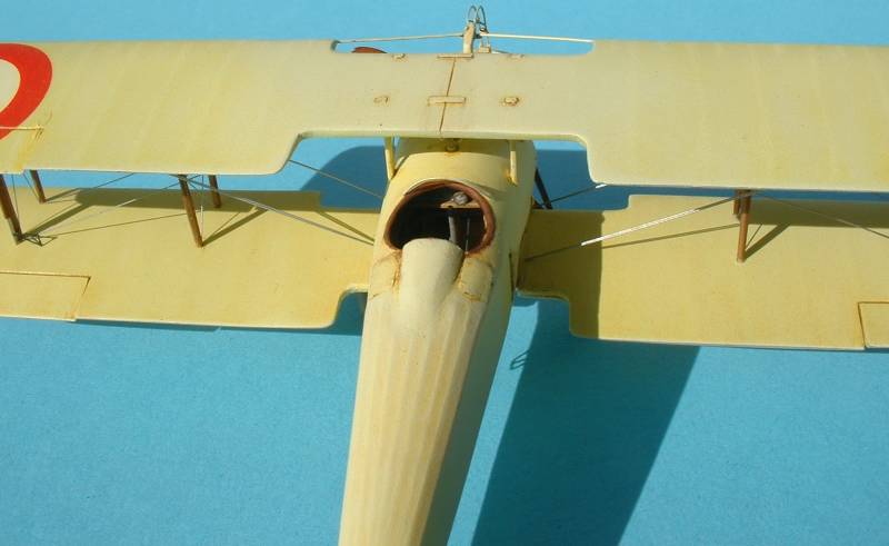
 At
the same time I worked on the pilot's cockpit, I also worked on the inside
of the nacelle. Since there are no known photos of the gunner's cockpit,
anything could practically go. After thinning the inside I added some
structure with doubled-up wood-grain decals then added an Omega Russian
camera to make this more of a reconnaissance machine than a fighter. Since
I didn't like the kit seat I added a resin Rosemont seat to complete the
inside of the nacelle. Remember the theme of this article? Instead of
the tedious task of thinning the floor of the nacelle - since I was going
to drill and cut out the plastic for the underside window - I cut away
the floor and replaced with .015" thick sheet styrene. I glued on
the floor at the same time I glued the nacelle halves together. Now all
struts on the nacelle were thinned considerably before this was set aside. At
the same time I worked on the pilot's cockpit, I also worked on the inside
of the nacelle. Since there are no known photos of the gunner's cockpit,
anything could practically go. After thinning the inside I added some
structure with doubled-up wood-grain decals then added an Omega Russian
camera to make this more of a reconnaissance machine than a fighter. Since
I didn't like the kit seat I added a resin Rosemont seat to complete the
inside of the nacelle. Remember the theme of this article? Instead of
the tedious task of thinning the floor of the nacelle - since I was going
to drill and cut out the plastic for the underside window - I cut away
the floor and replaced with .015" thick sheet styrene. I glued on
the floor at the same time I glued the nacelle halves together. Now all
struts on the nacelle were thinned considerably before this was set aside.
It was at this time - naturally - that the Part photoetch (p/e) set
was released. This is an awesome p/e set, probably the best I've seen
from Part yet. I obtained the Part set, at first to guide me with the
rest of construction, but in the end I ended up using a lot of the exterior
pieces provided.
 Now
that I had the fuselage halves assembled it was time to move on. Amodel
was very intelligent when it molded this kit. They molded - in situ -
the center section struts and the main landing gear legs with the side
cheeks. This was an extremely intelligent decision in that it provides
a very strong assembly. All of the other SPAD 'pulpit' models I have seen
have all of these struts being "butt-joined", resulting in a
kit that won't be as strong as the Amodel. Before I glued on the cheek/strut
pieces, though, I thinned the inside of the cheeks. If you don't sand
the inside of the cheeks they won't have the typical "see through"
(if you actually can) effect that was evident on the real thing. So, using
the trusty, cordless Dremel I thinned the inside of the cheeks. Not all
the way, but enough to provide the right effect without sacrificing any
of the strength inherent in the kit parts. This is one area that I personally
wouldn't use the Part p/e for. Part has you cut off the struts from the
cheeks and replace the plastic cheeks with photoetch pieces. This is no
better - strength wise - than any of the other 'pulpit' kits. Once I glued
on the cheeks - using a combination of liquid cement and CA - I then drilled
out the kit's representation for the carburetor intake pipes (important
to note that these are not exhausts). Now
that I had the fuselage halves assembled it was time to move on. Amodel
was very intelligent when it molded this kit. They molded - in situ -
the center section struts and the main landing gear legs with the side
cheeks. This was an extremely intelligent decision in that it provides
a very strong assembly. All of the other SPAD 'pulpit' models I have seen
have all of these struts being "butt-joined", resulting in a
kit that won't be as strong as the Amodel. Before I glued on the cheek/strut
pieces, though, I thinned the inside of the cheeks. If you don't sand
the inside of the cheeks they won't have the typical "see through"
(if you actually can) effect that was evident on the real thing. So, using
the trusty, cordless Dremel I thinned the inside of the cheeks. Not all
the way, but enough to provide the right effect without sacrificing any
of the strength inherent in the kit parts. This is one area that I personally
wouldn't use the Part p/e for. Part has you cut off the struts from the
cheeks and replace the plastic cheeks with photoetch pieces. This is no
better - strength wise - than any of the other 'pulpit' kits. Once I glued
on the cheeks - using a combination of liquid cement and CA - I then drilled
out the kit's representation for the carburetor intake pipes (important
to note that these are not exhausts).
Construction then moved back to the nacelle. Prior to using the Part
photoetch set, I was sent some other photoetch mesh by Andrei Koribanics
that would have looked great installed. Because of this I created semi-recessed
"holes" where the mesh would go to give it more of a "hollow"
look. However, since I decided to use the Part p/e I used the photoetched
nacelle sides. I believe the reason why (at least in my opinion) 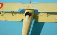 the
Part mesh looks good on my model was because of these "holes"
I carved in. Part etched the nacelle sides - for some reason - with "framing"
around the outside of the sides. This didn't exist on the real thing,
so I thought I would be smart and flip them, meaning the framing was glued
to the nacelles. This was a bad idea, in that any pressure added to the
p/e sides meant they "squished" in. Fixing that was a major
pain. There are two alternatives to my "barbaric method" I used
to fix these. You could either be sure to fill the entire p/e with glue
as you put it down reversed - so the glue fills the area between the framing,
or you could sand away the framing either before or after installation.
Next time I put one of these together (probably when I'm retired) I'll
try to sand the framing away. the
Part mesh looks good on my model was because of these "holes"
I carved in. Part etched the nacelle sides - for some reason - with "framing"
around the outside of the sides. This didn't exist on the real thing,
so I thought I would be smart and flip them, meaning the framing was glued
to the nacelles. This was a bad idea, in that any pressure added to the
p/e sides meant they "squished" in. Fixing that was a major
pain. There are two alternatives to my "barbaric method" I used
to fix these. You could either be sure to fill the entire p/e with glue
as you put it down reversed - so the glue fills the area between the framing,
or you could sand away the framing either before or after installation.
Next time I put one of these together (probably when I'm retired) I'll
try to sand the framing away.
While I used 3/4ths of the p/e parts meant for the nacelle, I didn't
use the replacement steps that mounted on and between the underside struts.
These I replaced with wire. I also added the p/e frame that went around
the underside window (which I used Kristal Kleer to fill after final model
completion).
For the struts on the underside of the horizontal tail I drilled holes
all the way through the fuselage and replaced the kit parts with .010"
thick Plastruct rod and bent them into shape. This worked extremely well,
and drilling all the way through made sure that both sides were aligned
correctly. I removed all control surfaces, posing them dynamically before
starting to paint.
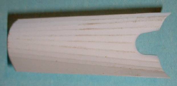
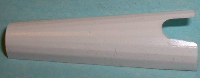
 Since
Amodel's "stringered" effect on the upper turtledeck was poorly
molded - and didn't exist on the fuselage underside - I replaced the "stringered"
effect with sheet plastic "embossed" with the stringers from
the inside (I believe Harry Woodman was the first to pioneer this technique).
What I did was photocopy the plans from the Mini-Datafile (actually the
drawings for the A.4 and not the A.2) and cut out the turtledeck areas
from the photocopies. I then temporarily tacked these plans to a sheet
of styrene, and using a metal ruler and the back edge of an Xacto #10
blade (being sure the edge is flat and perpendicular to the plastic),
I "pushed" on the plastic using the ruler as a guide set on
the drawn lines representing the stringers. After done with all "stringered
lines" I flipped the plastic over, and that's the side that sits
up - the side that was "pushed in" is the side you glue to the
fuselage. This took four attempts - the first two didn't turn out well,
the third attempt I used the wrong glue, and the fourth attempt was the
keeper. You could use either CA or epoxy to glue the new turtledecks on
- I Since
Amodel's "stringered" effect on the upper turtledeck was poorly
molded - and didn't exist on the fuselage underside - I replaced the "stringered"
effect with sheet plastic "embossed" with the stringers from
the inside (I believe Harry Woodman was the first to pioneer this technique).
What I did was photocopy the plans from the Mini-Datafile (actually the
drawings for the A.4 and not the A.2) and cut out the turtledeck areas
from the photocopies. I then temporarily tacked these plans to a sheet
of styrene, and using a metal ruler and the back edge of an Xacto #10
blade (being sure the edge is flat and perpendicular to the plastic),
I "pushed" on the plastic using the ruler as a guide set on
the drawn lines representing the stringers. After done with all "stringered
lines" I flipped the plastic over, and that's the side that sits
up - the side that was "pushed in" is the side you glue to the
fuselage. This took four attempts - the first two didn't turn out well,
the third attempt I used the wrong glue, and the fourth attempt was the
keeper. You could use either CA or epoxy to glue the new turtledecks on
- I  opted
for CA only because I don't like the smell of epoxy. One thing you might
want to do is fill in all the engraved lines with CA so when you're handling
the model you won't accidentally push back in one of the embossed "stringers".
I created a new "turtledeck" (turtlebottom? turtlebelly?) not
only for the top but the underside as well. opted
for CA only because I don't like the smell of epoxy. One thing you might
want to do is fill in all the engraved lines with CA so when you're handling
the model you won't accidentally push back in one of the embossed "stringers".
I created a new "turtledeck" (turtlebottom? turtlebelly?) not
only for the top but the underside as well.
After I thinned the wings on the underside I scribed in lines to represent
the rib locations. Once that was finished I added the lower wings to the
fuselage as well as the horizontal tailpieces.
Prior to painting I also wanted to add the "fishplate" photoetch
pieces that represent the plates that connect the landing gear and underside
struts to the main assembly. I also added a new cross-rod to the underside
nacelle struts since the kit one wasn't well molded in my kit. Plus I
scratched a new undercarriage "axle wing" between the main landing
gear struts as I destroyed the kit one trying to clean it up, and every
picture I saw of the A.2 showed that this was actually covered and not
left open as the kit part represents.
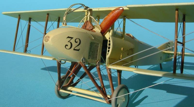
Final Assembly and Painting
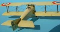
 Now
I could proceed with painting. I used Mister Kit paints exclusively -
their French CDL and French Yellow, both very decent colors. After painting
both colors was finished I started on the weathering as well as painting
the struts wood - all but the center struts, which were left Yellow. Once
dry the struts were subject to "graining" with two applications
of oil colors - Raw Umber and Burnt Sienna. The main assembly was also
weathered primarily with oils, but also with watercolor pencils, which
were used to highlight the "high" areas, such as ribs and stringers.
It was actually difficult to highlight the wing ribs because there was
very little relief to the plastic; in other words the ribs weren't very
pronounced. Now
I could proceed with painting. I used Mister Kit paints exclusively -
their French CDL and French Yellow, both very decent colors. After painting
both colors was finished I started on the weathering as well as painting
the struts wood - all but the center struts, which were left Yellow. Once
dry the struts were subject to "graining" with two applications
of oil colors - Raw Umber and Burnt Sienna. The main assembly was also
weathered primarily with oils, but also with watercolor pencils, which
were used to highlight the "high" areas, such as ribs and stringers.
It was actually difficult to highlight the wing ribs because there was
very little relief to the plastic; in other words the ribs weren't very
pronounced.
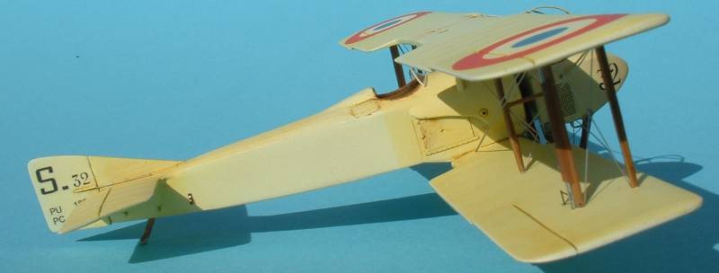
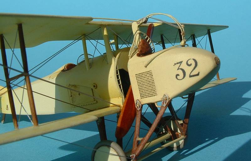
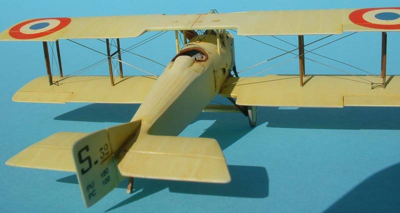
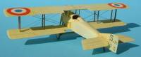
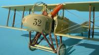
After initial weathering was accomplished I sprayed a coat of Future
over everything to get the model ready for decaling. The roundels came
from the kit while the rudder serial and nacelle number were ALPS generated.
Once the decals were dry then another coat of Future was brushed over
them to seal them in. Now I could attach the upper wing using the kit
struts. The major point of modification here is with the outer wing strut
closest to the trailing edge. Sitting perpendicular to the strut is the
actuating mechanism for the lower wing ailerons. Amodel doesn't have this
quite right but luckily Part provides the "sheath" that "envelops"
the actuating strut. This was added to the strut prior to painting and
was given a coat of brown to represent leather. (It appears that on the
later SPADs this was actually made of metal, but not on the A-series.)
 Since
the center struts are in-situ with the fuselage the upper wing was attached
to them first. I found I had to deepen the holes on the upper wing where
the center struts were to attach to. After this was dry I started with
the inner most struts and pushed them into place. (In all actuality these
aren't struts, but instead are used to keep the rigging separated and
in the right spots.) Once relatively dry then the outer most struts were
glued on, being sure to capture the aileron-actuating rod with the trailing
edge strut. Since
the center struts are in-situ with the fuselage the upper wing was attached
to them first. I found I had to deepen the holes on the upper wing where
the center struts were to attach to. After this was dry I started with
the inner most struts and pushed them into place. (In all actuality these
aren't struts, but instead are used to keep the rigging separated and
in the right spots.) Once relatively dry then the outer most struts were
glued on, being sure to capture the aileron-actuating rod with the trailing
edge strut.
Now that the upper wing was added I wanted until it was dry and glued
on the scratched axle fairing and wheels to the landing gear struts. Now
it was time to glue on the nacelle. The struts leading from the upper
wing to the nacelle were scratched, and this area I have a little bit
wrong. It's easy to tell that these struts are airfoil shaped instead
of the round rod I used. Oh well, something I have to live with now.
Part is ingenious with the nacelle. With the proper mounting of all
their p/e brackets and fishplates, you can actually have the nacelle move
"on and off" ("up and down") the main airframe. Unfortunately
I was growing tired of this model and wanted it finished so I opted not
to try this. Still, it's something to consider if you have the time and
patience. It would definitely be a conversation piece later on. (Imagine
a contest judge's surprise when he or she looks at the model at one point
with the nacelle up, and then when he or she comes back and the nacelle
is down. Maybe this will stop judges from picking up models <snicker>.).
 I
used a Martin Digmayer real-wood, carved prop, which was added before
the nacelle was stuck on, and the only exterior piece missing from the
Part fret were the leather handles used to lift the tail up, which are
located toward the tail, about midway down the fuselage. Before assembly
began I marked the locations of these with #80 drill holes. I then used
some left over p/e brass seat belts to make these handles, painted them
leather and glued them on. The leather headrests in both cockpits were
formed from epoxy putty, glued onto each part and painted and weathered. I
used a Martin Digmayer real-wood, carved prop, which was added before
the nacelle was stuck on, and the only exterior piece missing from the
Part fret were the leather handles used to lift the tail up, which are
located toward the tail, about midway down the fuselage. Before assembly
began I marked the locations of these with #80 drill holes. I then used
some left over p/e brass seat belts to make these handles, painted them
leather and glued them on. The leather headrests in both cockpits were
formed from epoxy putty, glued onto each part and painted and weathered.
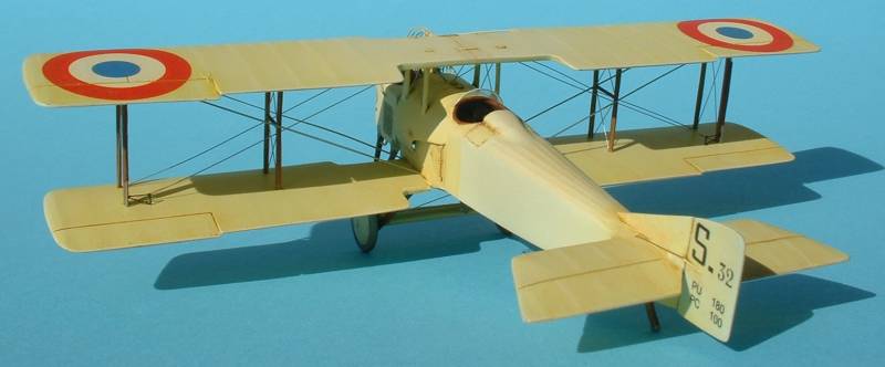
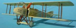
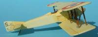
Conclusion
The Amodel SPAD A.2/A.4 is the most accurate of all the pulpit kits
out there. However, it will take some work to build this. Don't let that
stop you, though. Coupled with the Part photoetch set and plenty of patience
(and sandpaper) this can be made into a stunning model.
Acknowledgements
My thanks to Diego Fernetti for the drawing of what the nacelle's interior
might have looked like. Witold Kozakiewicz for creating the Part photoetch
set. Part for supplying the photoetch set. Erik Pilawskii for the ALPS
decals. Pedro Soares and Steven Perry for being patient with me (and letting
me know it). Rosemont for supplying their seats. And finally to the rest
of the WW1 modeling email list for the camaraderie and the general help
during all WW1 builds.
References
Davilla, Dr. James J. and Arthur M. Soltan, French Aircraft of the
First World War, Flying Machines Press, 1997.
Avions #46-50 and 70
Windsock Mini-Datafile #4 SPAD S.A-2/S.A-4.
WW1 Aero #s 117, 127 and 180
|
|