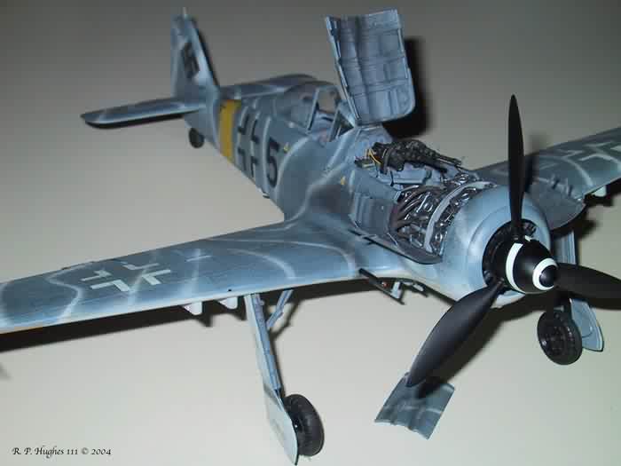
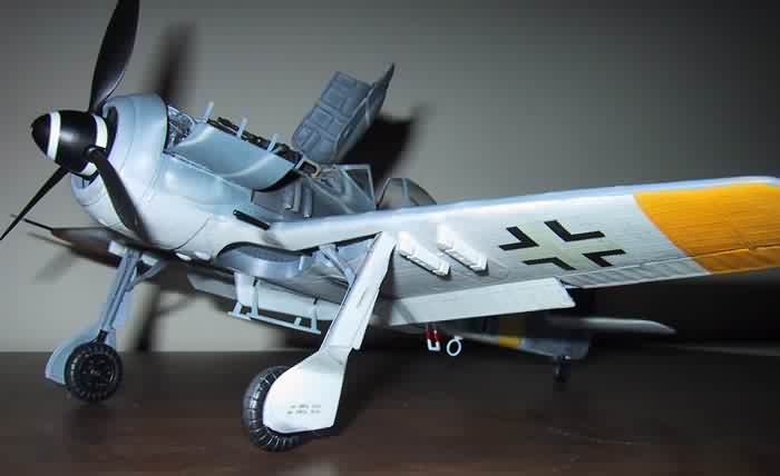
Revell 1/32 scale FW190F-8
|
 |
FW 190 F-8
 There
has been plenty written about the FW-190 that I won’t repeat here.
Briefly the FW-190 F-8 was the radial engine version modified for ground
attack missions. It had hard points on the center fuselage and wings to
carry fuel and ordinance. There
has been plenty written about the FW-190 that I won’t repeat here.
Briefly the FW-190 F-8 was the radial engine version modified for ground
attack missions. It had hard points on the center fuselage and wings to
carry fuel and ordinance.
THE KIT
 When
I opened the Revell F-8 kit I quickly realized that this was a repop of
the Hasegawa A-8 that was originally issued in the early 70’s. In
fact I have an unbuilt Hasegawa FW 190 A-8 kit in my stash that I bought
in 1975 and I compared the two. Even the mold blemishes on the inside
of the wings were identical. Revell has substituted parts to complete
the F-8 version. When
I opened the Revell F-8 kit I quickly realized that this was a repop of
the Hasegawa A-8 that was originally issued in the early 70’s. In
fact I have an unbuilt Hasegawa FW 190 A-8 kit in my stash that I bought
in 1975 and I compared the two. Even the mold blemishes on the inside
of the wings were identical. Revell has substituted parts to complete
the F-8 version. 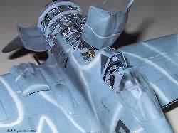 These
include a new late type canopy that accurately shows the armored windscreen.
The canopy has a late type headrest and the rear portion of the canopy
is “blown”. It is nicely molded and quite clear. Other upgrade
parts include a new instrument panel, larger wing bulges for the cannon,
and wing hard points for the bombs included in the kit. Although the These
include a new late type canopy that accurately shows the armored windscreen.
The canopy has a late type headrest and the rear portion of the canopy
is “blown”. It is nicely molded and quite clear. Other upgrade
parts include a new instrument panel, larger wing bulges for the cannon,
and wing hard points for the bombs included in the kit. Although the 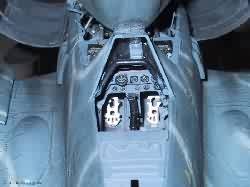 cockpit
detail is a little sparse, it does include a nice rendition of the BMW
801 14 cylinder radial engine. That is one of the reasons I decided to
use the Verlinden upgrade. The other reason was I had never worked with
resin or photo etch before and wanted to give it a try. The kit has raised
detail throughout, as was the standard back then. For more info on this
kit there is an cockpit
detail is a little sparse, it does include a nice rendition of the BMW
801 14 cylinder radial engine. That is one of the reasons I decided to
use the Verlinden upgrade. The other reason was I had never worked with
resin or photo etch before and wanted to give it a try. The kit has raised
detail throughout, as was the standard back then. For more info on this
kit there is an  excellent
review of this Revell repop in our September
2001 issue. excellent
review of this Revell repop in our September
2001 issue.
Rather than sand off all the detail and rescribe the panel lines, I decided
to go with the raised detail. I did sand the detail lightly to make it
less pronounced. I decided to upgrade the model with the Verlinden resin
and photo etch kit  number
1675. This kit includes a resin cockpit, fuselage MG 151s, injection tank,
radio compass and engine detail parts. The fit of this kit is rough for
a Hasegawa. There is a large gap where the wing and engine cowling meet.
There is also a sizable gap where the wing and the fuselage meet at the
rear. The wing roots require a little bit of filling and the fuselage
itself took a little putty number
1675. This kit includes a resin cockpit, fuselage MG 151s, injection tank,
radio compass and engine detail parts. The fit of this kit is rough for
a Hasegawa. There is a large gap where the wing and engine cowling meet.
There is also a sizable gap where the wing and the fuselage meet at the
rear. The wing roots require a little bit of filling and the fuselage
itself took a little putty  too.
The fit is not all that bad, but if you are used to the fit of the new
tool Bf-109 or the new tool FW-190D you are in for a bit of a surprise.
This kit takes a lot of test fitting, sanding and filling compared to
those new kits. It can be built up into a very nice model though. too.
The fit is not all that bad, but if you are used to the fit of the new
tool Bf-109 or the new tool FW-190D you are in for a bit of a surprise.
This kit takes a lot of test fitting, sanding and filling compared to
those new kits. It can be built up into a very nice model though.
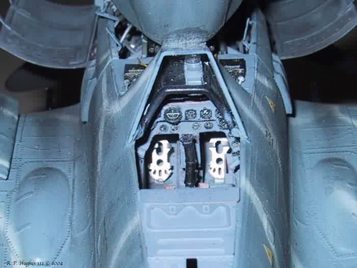
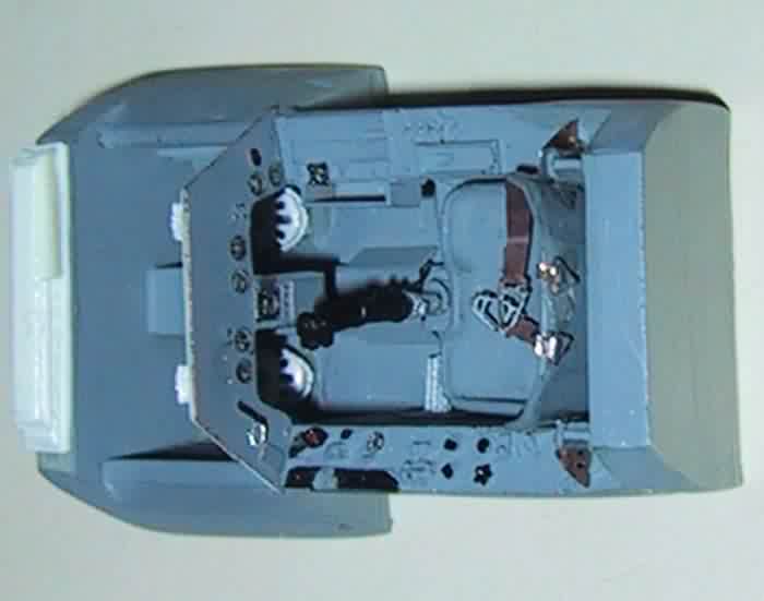
 I
started with the cockpit. The Verlinden cockpit has a detailed tub and
numerous resin and photo etched detail parts to add to the tub. The instrument
panel is a photo etched surface with holes in the appropriate places for
the artificial horizon, tach, and other gauges. Behind the photo etched
piece you place a clear piece of acetate that has all the dials and numbers
for the gauges printed on the surface. The back of this clear piece can
be painted the appropriate color for each gauge. For most of the gauges
this is white and makes the gauge detail really stand out. The clear piece
and photo etch panel surface is glued to a background in the shape of
the instrument panel. I fabricated this part from a piece of flat plastic
stock. I used the kit part for the general shape. The detail and crispness
of the Verlinden resin parts is good, but some of the parts had pinholes
that had to be addressed. Depending on the part, I used either Squadron
putty or gap filling superglue to fill them. I painted the interior a
medium gray. I tried to match the color as close as I could with the pictures
of the 190 A-8 on the excellent Hyperscale reference page. For you folks
that have not discovered that web page yet, definitely check it out at
Hyperscale. I
started with the cockpit. The Verlinden cockpit has a detailed tub and
numerous resin and photo etched detail parts to add to the tub. The instrument
panel is a photo etched surface with holes in the appropriate places for
the artificial horizon, tach, and other gauges. Behind the photo etched
piece you place a clear piece of acetate that has all the dials and numbers
for the gauges printed on the surface. The back of this clear piece can
be painted the appropriate color for each gauge. For most of the gauges
this is white and makes the gauge detail really stand out. The clear piece
and photo etch panel surface is glued to a background in the shape of
the instrument panel. I fabricated this part from a piece of flat plastic
stock. I used the kit part for the general shape. The detail and crispness
of the Verlinden resin parts is good, but some of the parts had pinholes
that had to be addressed. Depending on the part, I used either Squadron
putty or gap filling superglue to fill them. I painted the interior a
medium gray. I tried to match the color as close as I could with the pictures
of the 190 A-8 on the excellent Hyperscale reference page. For you folks
that have not discovered that web page yet, definitely check it out at
Hyperscale.
It is a very interesting interactive reference for the FW 190 interior.
I added a harness made from paper and added the buckles from the Verlinden
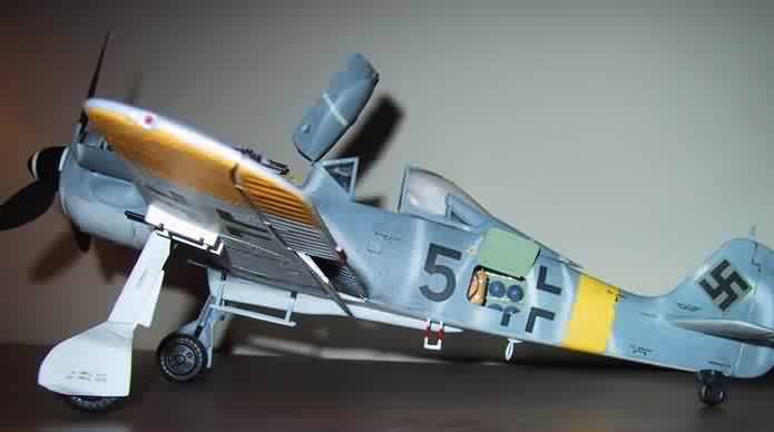
set. After I had painted and completed the tub, I then began to 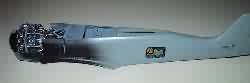 work
on the fuselage. This requires quite a bit of work. A Dremel tool or similar
grinder is essential here. First, I opened up the radio access door on
the left hand side of the fuselage. I used the work
on the fuselage. This requires quite a bit of work. A Dremel tool or similar
grinder is essential here. First, I opened up the radio access door on
the left hand side of the fuselage. I used the 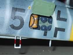 grinder
to remove material and slowly thin the fuselage behind the door from the
inside. This must be done very carefully. One trick I learned is as you
remove material hold the part up to a light source. As you get it thinned
enough the part becomes translucent. Continue to thin the inside of the
fuselage until light can be seen through the part. When you are satisfied
the part is thinned enough, carefully cut the door out of the grinder
to remove material and slowly thin the fuselage behind the door from the
inside. This must be done very carefully. One trick I learned is as you
remove material hold the part up to a light source. As you get it thinned
enough the part becomes translucent. Continue to thin the inside of the
fuselage until light can be seen through the part. When you are satisfied
the part is thinned enough, carefully cut the door out of the  fuselage.
Don’t worry about the door. It will be replaced by a photo etched
part in the Verlinden kit. In fact, it is wise to cut the door a little
on the inside of the line defining the door. After it has been removed
you can slowly enlarge the opening with a sanding stick. I painted the
interior of the rear fuselage interior green using Tamiya IJN interior
green mixed with some flat white to lighten the color. fuselage.
Don’t worry about the door. It will be replaced by a photo etched
part in the Verlinden kit. In fact, it is wise to cut the door a little
on the inside of the line defining the door. After it has been removed
you can slowly enlarge the opening with a sanding stick. I painted the
interior of the rear fuselage interior green using Tamiya IJN interior
green mixed with some flat white to lighten the color.
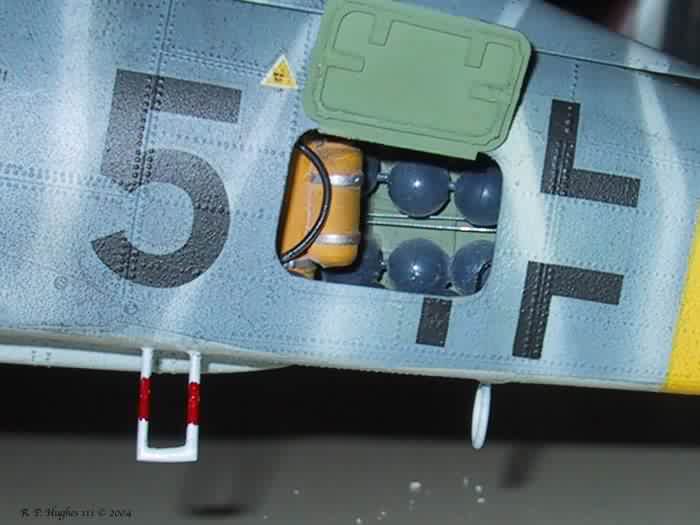
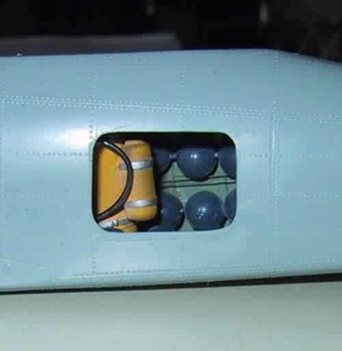
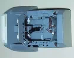
The next step was to prepare the items to go into the rear fuselage
that will be visible through the open radio access door. The MW 50 injection
tank is very nicely done. There were no bubbles or pits in the tank resin.
I painted it yellow and added the connection hoses fashioned from lead
solder wire. I use this because it is quite malleable and easy to paint.
I made the blue oxygen tanks from beads I purchased from the local arts
and crafts store. I strung and glued three beads each on some beading
wire. I then painted them blue as called for in the references I was using.
I then added the interior stringers to the fuselage from the photo etched
parts of the Verlinden kit. I added control wires and tail wheel cable
from wire stock. These could be seen on the real aircraft when the access
door was open. With all the parts in the rear fuselage in place I glued
the two halves of the fuselage together. Very little putty was required
for he fuselage joint.
 After
the fuselage was joined together, I removed the instrument panel cowling.
Verlinden supplies a replacement cowling that is much more accurate than
the one on the kit. I used the panel line on the surface of the fuselage
as a guide. Be very careful when you do this. Remember, you can always
remove more After
the fuselage was joined together, I removed the instrument panel cowling.
Verlinden supplies a replacement cowling that is much more accurate than
the one on the kit. I used the panel line on the surface of the fuselage
as a guide. Be very careful when you do this. Remember, you can always
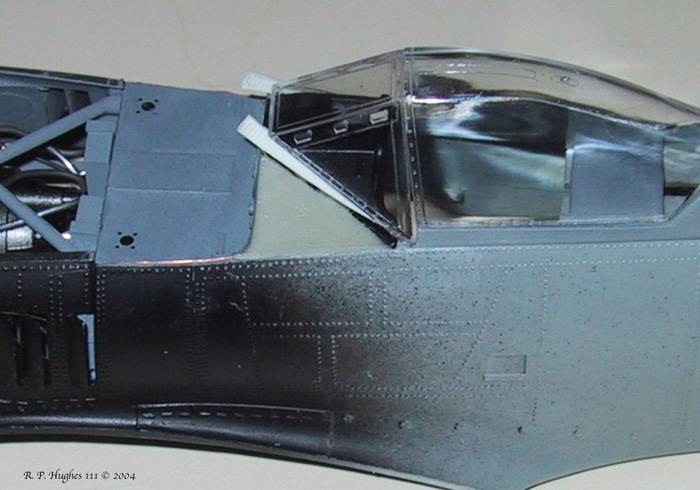
remove more 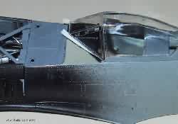 material,
but it is very difficult to put it back once you have removed it. I accidentally
removed more material than I should have. As you can see in the picture,
I had to cut small shims out of plastic and insert them between the forward
canopy clear piece and the resin instrument cowing to obtain the correct
location of the material,
but it is very difficult to put it back once you have removed it. I accidentally
removed more material than I should have. As you can see in the picture,
I had to cut small shims out of plastic and insert them between the forward
canopy clear piece and the resin instrument cowing to obtain the correct
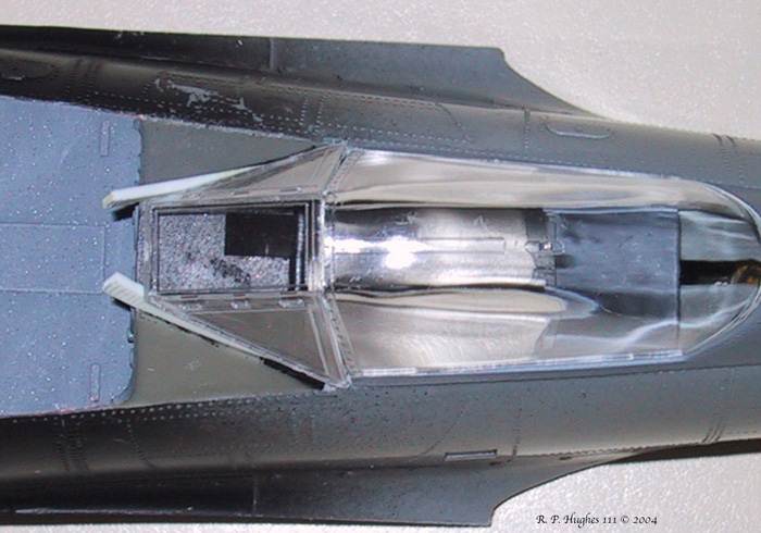
location of the 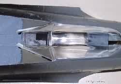 forward
cockpit clear piece in relation to the rest of the canopy. I used Squadron
putty to fill the area below the front canopy and sanded the joint between
the fuselage and the instrument panel cowling. Next I installed the upper
instrument panel in the appropriate location on the underside of the resin
instrument cowling. I cut two small gun sight reflectors from the same
acetate sheet that contained the instrument gauges. I used CA glue to
attach them to the resin gun sight from the Verlinden kit and then glued
the gun sight to the instrument panel. Next I placed the cockpit tub into
the fuselage from underneath through the hole where the wings are attached.
I added the photo etched gun compartment floor to the fuselage forward
of the cockpit. The fuselage guns were painted Tamiya Acrylic gunmetal
and mounted atop the plate. The electronic control boxes from the Verlinden
set were added. Wiring was added using solder wire. Again it is malleable
and can be painted colors to represent insulation. forward
cockpit clear piece in relation to the rest of the canopy. I used Squadron
putty to fill the area below the front canopy and sanded the joint between
the fuselage and the instrument panel cowling. Next I installed the upper
instrument panel in the appropriate location on the underside of the resin
instrument cowling. I cut two small gun sight reflectors from the same
acetate sheet that contained the instrument gauges. I used CA glue to
attach them to the resin gun sight from the Verlinden kit and then glued
the gun sight to the instrument panel. Next I placed the cockpit tub into
the fuselage from underneath through the hole where the wings are attached.
I added the photo etched gun compartment floor to the fuselage forward
of the cockpit. The fuselage guns were painted Tamiya Acrylic gunmetal
and mounted atop the plate. The electronic control boxes from the Verlinden
set were added. Wiring was added using solder wire. Again it is malleable
and can be painted colors to represent insulation.
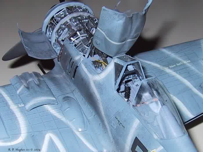
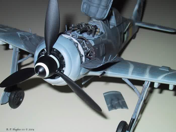
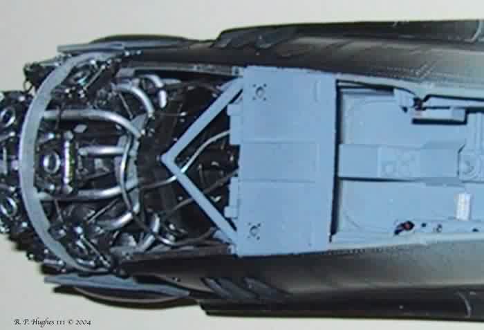
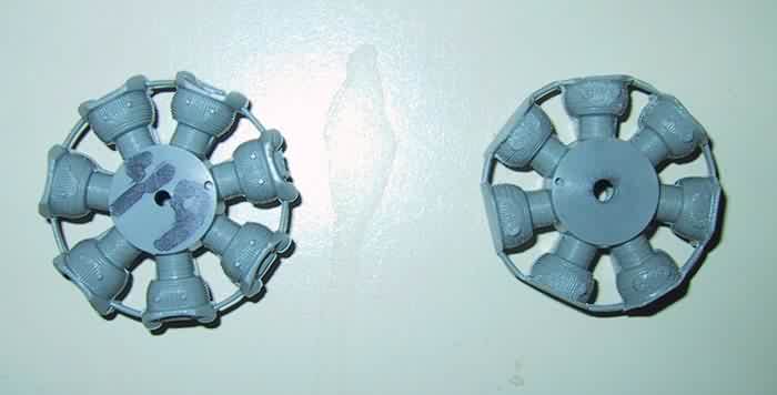
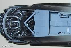
 I
then assembled the BMW 801 Radial engine from the kit. First I glued the
two halves of the cylinders together. Next I shaved 1 mm off the top of
each cylinder head and added the replacement heads form the Verlinden
kit. After this was done I positioned and drilled two spark plug holes
in each cylinder head. Here again, I used solder wire to represent the
plug wires. I
then assembled the BMW 801 Radial engine from the kit. First I glued the
two halves of the cylinders together. Next I shaved 1 mm off the top of
each cylinder head and added the replacement heads form the Verlinden
kit. After this was done I positioned and drilled two spark plug holes
in each cylinder head. Here again, I used solder wire to represent the
plug wires.
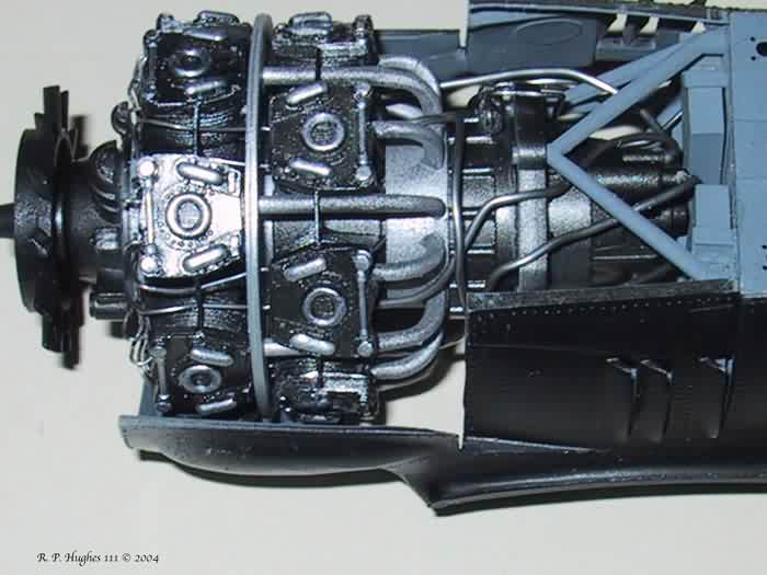
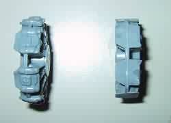
 The
wires are attached to the head and run to the kit wire harness mounted
on front of the propeller gearbox. I removed the plastic braces between
the individual cylinder heads because they looked too thick and out of
scale. They were replaced with wire stock. The engine was painted The
wires are attached to the head and run to the kit wire harness mounted
on front of the propeller gearbox. I removed the plastic braces between
the individual cylinder heads because they looked too thick and out of
scale. They were replaced with wire stock. The engine was painted 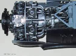 gunmetal
and given a wash of flat black. I then dry brushed the high points with
aluminum paint. It was mounted to the front of the fuselage with the kit
supplied engine mount. gunmetal
and given a wash of flat black. I then dry brushed the high points with
aluminum paint. It was mounted to the front of the fuselage with the kit
supplied engine mount.
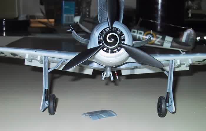
The bottom of the wing was added to the top wing halves.
The kit supplied wing cannons were replaced with brass tubing cut to length.
I also had to drill from the hole in the front of the wing through the
wheel well so the cannon barrel (brass tube) could go through the well
into the wing where the cannons were mounted. For some reason Hasegawa
left this detail off. The wings and the front of the engine cowling were
then added. Verlinden supplies nice photo etched replacements for the
engine cowling doors. They are flat on the photo etch sprue and need to
be rounded to the shape of the fuselage. I shaped the photo etched cowlings
by first placing them on the model fuselage part itself. This gets the
curve of the door close to the desired shape. Next I gently rolled the
photo etched cowling replacement a few times on a cylinder shape. This
increases the curvature. When the curvature is correct I placed the cowling
in the closed position for painting the fuselage. Then I masked the canopy
with Tamiya tape.
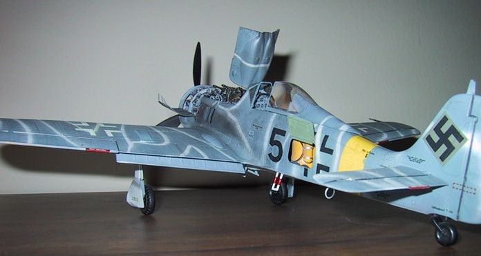
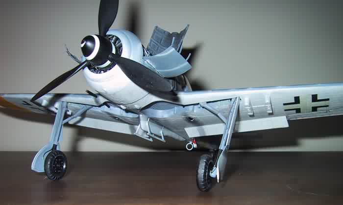
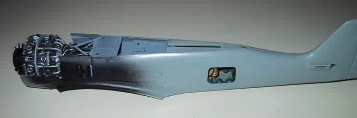
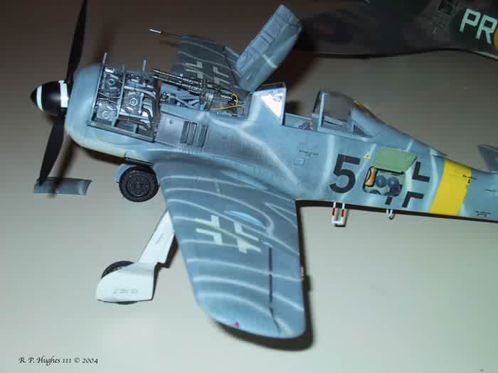
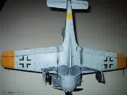
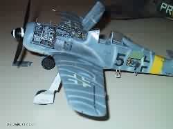
I
decided to paint and decal the plane as the FW 190 F-8 in Hungary July
of 1944 provided in the kit. The scheme called for a RLM 74 gray with
RLM 76 lines across the surface. I used Testors Acrylics and lightened
the base color a bit. I puzzled about how to obtain the effect of the
lines that I wanted. They appeared to be thin but without sharp demarcation
lines between the RLM
76 and the base gray. I painted the surface RLM 76. Then I placed thin
strips of Silly Putty on the surface that would remain the RLM 76 stripes.
I then painted the surface gray with an airbrush, keeping enough distance
and angle on the Silly Putty to give a soft  demarcation
line. I lightened the color with some white to show fading and to get
a bit of scale effect. Let me say one thing about painting before you
say that I got the colors wrong. I paint the colors as I see ‘em.
Sure I try to be accurate and try to get them close to how the original
looked. Keep in mind that is a judgment demarcation
line. I lightened the color with some white to show fading and to get
a bit of scale effect. Let me say one thing about painting before you
say that I got the colors wrong. I paint the colors as I see ‘em.
Sure I try to be accurate and try to get them close to how the original
looked. Keep in mind that is a judgment 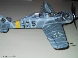 call.
Most photos from that era are in black and white. Additionally, color
photos deteriorate over time. Color film was in its infancy at the time
of World War II. At that time it was not generally known that the color
photos being taken would deteriorate and thus little was done to properly
preserve the negatives. Those color photos have deteriorated and cannot
truly be trusted to show the colors the human eye saw at the time. So
please, any constructive criticism is welcome, but keep in mind that model
making is an art and this is my interpretation. call.
Most photos from that era are in black and white. Additionally, color
photos deteriorate over time. Color film was in its infancy at the time
of World War II. At that time it was not generally known that the color
photos being taken would deteriorate and thus little was done to properly
preserve the negatives. Those color photos have deteriorated and cannot
truly be trusted to show the colors the human eye saw at the time. So
please, any constructive criticism is welcome, but keep in mind that model
making is an art and this is my interpretation.
 After
the paint was dry I coated the surface with Testors Gloss Clear to get
a smooth surface to which the decals would adhere. You can also use Future
in this step. I used the kit decals. I got them to snuggle down on the
surface with Microscale Microsol decal solution. This is a strong solution
and settled the decals quit nicely. If you have never used a decal solvent
before, be After
the paint was dry I coated the surface with Testors Gloss Clear to get
a smooth surface to which the decals would adhere. You can also use Future
in this step. I used the kit decals. I got them to snuggle down on the
surface with Microscale Microsol decal solution. This is a strong solution
and settled the decals quit nicely. If you have never used a decal solvent
before, be 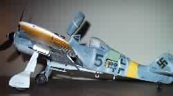 sure
not to touch the decals while they are drying. In fact they will wrinkle
up and look horrible while they are drying. They will settle down into
the recesses and detail as they dry. If you touch the decals while they
are drying they will disintegrate, so avoid the temptation. Once dry I
coated the model with Testors acrylic flat. After that was dry I weathered
the surface lightly. I first highlighted the raised detail with a number
2 lead drafting pencil. Next I ground up some pastel chalk. I used gray,
black, and burnt umber chalk and applied the dust with a dry brush. I
added exhaust marks along the side fuselage. I like to lay a black exhaust
stream first. Then inside that stream I add a smaller strip of gray dust.
It makes and effective and realistic looking exhaust residue. I have since
read that my technique is more accurate for the higher octane fuel the
United States Air Corps used. It seems that the Germans used lower octane
dirtier burning gas that left dark black exhaust trails. I also added
some on the bottom of the fuselage. I added some chalk dust to the inside
of the Verlinden cowling over the engine and over the MG 151. It could
probably stand some more weathering, as German planes at this time of
the war were used mercilessly. I decided to keep the weathering light
and add more later if I decided more was needed. One of the pluses of
the pastel chalk technique is if you over do it you can wipe it off with
a rag and start again before it is sealed. After you have gotten the chalk
weathering to your taste then seal it with one more light coat of Testors
Flat Acrylic. Another nice plus of this technique is one can always add
more later, even after it is sealed under the coat of flat acrylic. sure
not to touch the decals while they are drying. In fact they will wrinkle
up and look horrible while they are drying. They will settle down into
the recesses and detail as they dry. If you touch the decals while they
are drying they will disintegrate, so avoid the temptation. Once dry I
coated the model with Testors acrylic flat. After that was dry I weathered
the surface lightly. I first highlighted the raised detail with a number
2 lead drafting pencil. Next I ground up some pastel chalk. I used gray,
black, and burnt umber chalk and applied the dust with a dry brush. I
added exhaust marks along the side fuselage. I like to lay a black exhaust
stream first. Then inside that stream I add a smaller strip of gray dust.
It makes and effective and realistic looking exhaust residue. I have since
read that my technique is more accurate for the higher octane fuel the
United States Air Corps used. It seems that the Germans used lower octane
dirtier burning gas that left dark black exhaust trails. I also added
some on the bottom of the fuselage. I added some chalk dust to the inside
of the Verlinden cowling over the engine and over the MG 151. It could
probably stand some more weathering, as German planes at this time of
the war were used mercilessly. I decided to keep the weathering light
and add more later if I decided more was needed. One of the pluses of
the pastel chalk technique is if you over do it you can wipe it off with
a rag and start again before it is sealed. After you have gotten the chalk
weathering to your taste then seal it with one more light coat of Testors
Flat Acrylic. Another nice plus of this technique is one can always add
more later, even after it is sealed under the coat of flat acrylic.
This was a state of the art model back in early 70’s when it first
hit the shelves. The kit is showing its age but looks accurate dimensionally
and can be built into a nice model. It includes an engine and is the 190
to get, if you want to display the engine with an open cowling. There
is a rumor that Hasegawa is preparing to introduce a new tool FW 190A.
If you don’t want to put in the extra work you may be well advised
to wait for the new Hasegawa offering.
R.P. Hughes III © 2004
|
|